The following provides a basic methodology for using the
Camera step to
get live images from a camera:
-
If not already done automatically,
add a camera component to the platform.
-
Set the
source of the Camera step.
-
Optionally, manually
adjust the camera's focus. If you are running Matrox Design
Assistant in emulation mode or using image sets, skip this
step.
-
Optionally, configure your camera's
trigger settings.
-
Optionally, associate
a calibration file with the Camera step.
-
Optionally, specify remapping
settings.
To use the Camera step with a set of
images from file (image set), see the
Procedure for configuring image sets section in Chapter 29:
Acquisition using image sets. To use the Camera step with a series of
images taken from the camera during design-time, see the
Camera Images pane section in the
Panes and editors reference chapter.
When dealing with multiple cameras, refer to the Using multiple cameras section
later in this chapter.
When dealing with third-party sensors (for example, 3D sensors
that output depth maps), refer to
Chapter 37: Acquisition with third-party sensors.

 Adding a
camera to your project
Adding a
camera to your project
When creating a new project, select the camera type from the
dropdown list in the
New Project dialog. The correct camera and, if necessary,
system allocations will be made. If required, you can change the
camera type from the
Platform Configuration dialog, once the project is
created.
If your project requires multiple physical cameras, go to the
Platform Configuration dialog and add them using the
Cameras page. When adding a camera, you can select the
required type from the list of supported cameras. Any necessary
system allocations will also be done.
When using a PC runtime platform, Matrox Design Assistant only
supports GigE Vision and USB3 Vision compatible cameras. With
regards to line scan cameras, Matrox Design Assistant supports
GigE/USB3 Vision compatible line scan cameras that accumulate lines
into frames on the camera. Since these cameras output regular
images, Matrox Design Assistant can interface with them.
For more information on how to add a camera, see the
Cameras and your runtime platform section in
Chapter 2: Building a project.
Set the
source of the Camera step
The Camera
step can use images from the physical camera, images from file (an
image set), a series of images taken from the camera and reused
(design-time only), or a single image taken from the camera and
reused.
To specify a camera as the source of the Camera step, set the
Camera Source
input to PhysicalCameraN. The
Camera Source
input can also be changed using the
Camera Images pane. The list of all available Camera step sources are
presented as a dropdown list. To use an image set, see the
Procedure for configuring image sets section in Chapter 29:
Acquisition using image sets. To use a series of images taken
from the camera during design-time, see the
Camera Images pane section in the
Panes and editors reference chapter. To reuse the last grabbed
image, use the Trigger step; see the
Triggering
from a software trigger subsection of the Triggering section later in this chapter.
To change the source of the Camera step during runtime
(such as, to switch between the camera and saved images), use
platform configuration binding, the
CameraSettings step, or a link between a Button element and
the Set Camera
Source action. For more information, see the Changing the
acquisition settings at runtime section later in this
chapter.
For information on setting the Camera Source input for
multi-camera projects, see the Using multiple cameras section
later in this chapter.
Manually
adjust the camera's lens
At design-time, if your camera is out of focus, you can adjust
it by performing the following:
-
Select the Camera step. Then, click on
the
Camera Live ( ) toolbar button, in the
Project toolbar. The display refreshes to show a continuous
grab from your camera. Note that you can see a live image only if
triggering is not enabled (as configured on the PhysicalCameraN page of the
Platform Configuration dialog).
) toolbar button, in the
Project toolbar. The display refreshes to show a continuous
grab from your camera. Note that you can see a live image only if
triggering is not enabled (as configured on the PhysicalCameraN page of the
Platform Configuration dialog).
-
Adjust the image using the focus and aperture controls on the
lens of your camera.
-
Open the
Platform Configuration dialog to change the camera's inputs
(for example, exposure settings, gain settings, and partial scan
size). Such changes are immediately reflected in the live
image.
-
Click on the
Camera Live toolbar button again to stop the live grab.
-
Click on the Run
to the selected step button to update the Camera step's output
image.
Adjusting the camera's focus can also be done through the
operator view at runtime. To allow this, create an operator view
that includes input elements directly
bound to the required platform configuration settings or to a
CameraSettings step. Ensure that the operator view's
display is linked to the correct image (typically, Camera.Image). Configure an operator view
Button element so that the camera can be changed to continuous
grab mode (disables the Trigger input) and,
optionally, back to a triggered mode. The operator can then
interactively adjust the camera's settings while viewing the
effects. For an example, refer to the TrainingMain page of the
operator view in a template project (accessible from the Matrox
Design Assistant
Quick Start tab).
At runtime, with a supported Matrox smart camera and a liquid
lens, you can also focus your camera automatically; see the
Camera focus subsection of the
Grab and auxiliary I/O overview section in
Appendix D: Matrox Iris GTR.
Using
a continuous or triggered grab
Your project can be in either continuous grab or triggered grab
mode. When the Trigger input is disabled,
on the PhysicalCameraN page of the
Platform Configuration dialog, your project enters
continuous grab mode. With this setup, your camera will
continuously grab images in a background process. Each time that
your flowchart reaches the Camera step, a new image is
either taken from the image queue or the next available image is
taken. For more information, refer to the Continuous
grab mode with image queues subsection of the Grab timing section later in this
chapter.
When the Trigger input is enabled, on
the PhysicalCameraN page of the
Platform Configuration dialog, your project is in triggered
grab mode; your camera will only grab images when it receives a
trigger (either from the Trigger step, the operator
view, a hardware signal, or a PLC). Each time that your flowchart
reaches the Camera step, a new image is
taken from the image queue. For more information, refer to the
Triggering section later in this
chapter.
Associate a
calibration file with the Camera step
You can calibrate in X and Y for 2D images, and in Z for images
with 3D information, such as depth maps.
X/Y calibration
To work in calibrated world coordinates, you must associate a
calibration file with the Camera step before you
define any search regions or positions in your project. You can
define the calibration file with which to calibrate your camera
using the
Matrox Design Assistant configuration portal or using the
Calibration step.
If you are running Matrox Design Assistant in emulation mode, you
can choose from the calibration files stored in your project's
Platforms folder
(for example, \My
Documents\Matrox Design
Assistant\Projects\TargetProjectName\Platforms\Emulation\Calibrations.).
For more information, see Chapter 30:
Calibration.
Once a calibration file has been defined, set the Calibration input of the
Camera step to
the name of a calibration file. By default, all calibration files
associated with your project are listed in the dropdown list. To
load a different calibration file, click on the Alternate options button and
select Choose
calibration file from the fly-out menu.
Once a calibration file is associated with the Camera step, the
Camera step can
output the non-calibrated intensity image, Camera.Image, or its transformed version,
Camera.CorrectedImage. For the
transformation, you can specify the InterpolationMode input,
which controls the smoothness of edges and detail preserved, and
the Overscan
input, which determines how to deal with pixel values on the
perimeter of the image.
Note that, to work in real-world units, an image processing or
analysis step can use any of the Camera step's image outputs.
However, if your step needs a physically corrected image, you must
use the Camera.CorrectedImage
version.
Z calibration
Typically, depth maps are already calibrated in Z when acquired
from a third-party sensor. You can change the calibration using the
Properties pane with CustomZCalibration and
Zscale. For more
information on acquiring from a third-party sensor, refer to
Chapter 37: Acquisition with third-party sensors.
Remapping
Remapping is useful for images with bit depths greater than
8-bit. When enabled, the Camera step's remapping
settings specify how to convert the data to the right bit depth for
steps that link to the Camera step. You can choose
to remap the intensity image, or to remap a depth map, if
applicable. To configure remapping for a depth map, see
Working with depth maps.
To remap an intensity image, perform the following:
-
Choose the IMAGE
REMAP tab in the Camera step's
Configuration pane.
-
Check the Enabled checkbox to enable
remapping.
-
Optionally, select the gray level range. If no range is
specified, by default, all pixel intensity values are mapped to
span the full bit depth supported by the step linking to the camera
step.
To select a gray level range, in the IMAGE REMAP tab, manually
adjust the sliders, or choose a Start Mode and/or
End Mode from
the options below. Gray values not selected are saturated to the
low or high end of the specified range.
-
MinValue or
MaxValue.
Specifies to include the minimum or maximum pixel intensity level
as part of the selected gray level range.
-
Custom. Enter
a custom Start
Value or End
Value.
-
StdDev. Enter
a value equivalent to the number of standard deviations from the
mean for which you want to start or end the gray level range. The
default value is 1, which sets the start or end at 1 standard
deviation below or above the mean pixel intensity value.
When you enable remapping, any step that links to the
Camera step will
automatically map the selected range to the deepest bit depth that
the new step can handle. For example, if the subsequent step
requires 8-bit data, but the grabbed images are 16-bit, the
specified data values are mapped into 8-bit for the subsequent
step. Note that you can link directly to the Unsigned8Bit or Unsigned16Bit output image, if you want to
force a shallower depth.
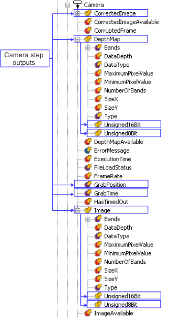
Accessing the Camera step's
outputs
The Camera
step outputs the grabbed images themselves, and other information
that allows you to monitor the grab. Note that both the original
grabbed data and the remapped versions (if remapping is enabled)
are available as outputs. The grabbed data can be intensity images
and/or depth maps.
The following camera outputs are related to grabbed images.
|
Camera output
|
Description
|
|
Camera.CorrectedImage
|
Returns the result of a calibration transformation applied to
the grabbed intensity image (Camera.Image).
|
|
Camera.DepthMap
|
Returns the depth map, according to remapping settings. If
remapping is enabled, returns the version of the depth map with the
deepest suitable bit depth for the step that requests it, either
Unsigned8Bit or Unsigned16Bit. If remapping is not enabled,
returns the unremapped depth map, with a bit depth and data type
provided by the 3D sensor. See
Chapter 38: Working with depth maps.
|
|
Camera.Image
|
Returns the grabbed intensity image, according to remapping
settings. If remapping is enabled, returns the version of the image
with the deepest suitable bit depth for the step that requests it,
either Unsigned8Bit or Unsigned16Bit. If remapping is not enabled,
returns the unremapped grabbed intensity image. See the Remapping
subsection of this section.
|
|
Camera.GrabPosition
|
Returns a rotary decoder's counter value at the moment at which
the image was grabbed. To obtain this result, set the Grab
reference source (grab time/position) input to
IOCommandList and use the rotary decoder as the command
list's counter source.
To retrieve the counter value of a rotary decoder or record the
timestamp of a hardware trigger, your runtime platform must have
access to a Matrox Advanced I/O Engine. For information on using a
rotary decoder or reading/recording a command list's counter value,
see the
Matrox Advanced I/O Engine section in
Chapter 40: IO steps.
|
|
Camera.GrabTime
|
Returns the timestamp at which the image was grabbed. This can
be used as a reference time for setting delays on output signals.
It can also be compared to the output of a
TimeStamp step or
PositionStamp step with a calculated elapsed value. The
timestamp used for the grab time is determined by the Grab
reference source (grab time/position) input on the
PhysicalCameraN page of the
Platform Configuration dialog.
Note that, on a Matrox 4Sight GPm runtime platform, the grab
synchronization option should be checked (on the
Cameras page of the
Platform Configuration dialog). Enabling grab
synchronization ensures that, even with one camera, the timestamp
remains synchronized with the actual moment the image is grabbed
(instead of the moment when the image starts being received). To
configure grab synchronization, see the
Grab synchronization with a reference stamp subsection of the
Matrox Advanced I/O Engine section in
Chapter 40: IO steps.
|