Cameras and your runtime platform
To set up the hardware and software components of your runtime platform for use within your project, use the Platform Configuration dialog.
This dialog is accessible by clicking on the Project Configure platform
menu item, or the
Configure platform ( ) toolbar button in the
Platform toolbar at the
top-right of the interface.
) toolbar button in the
Platform toolbar at the
top-right of the interface.
Note that, if you want to simultaneously run multiple projects on a runtime platform, and more than one of those projects grab from a camera, you must explicitly set, for each project, the camera allocation mode to a specific (and different) camera. For more information, see the Considerations when running multiple projects simultaneously section in Chapter 60: Running multiple projects on a runtime platform.
 Allocating cameras on a
PC runtime platform
Allocating cameras on a
PC runtime platform
New projects and nearly all existing projects have at least one Camera step. Each Camera step specifies a camera source, which is configured by selecting a camera component defined in the Platform Configuration dialog.
Each camera component maps to a physical camera and has its own unique configurable properties. The act of mapping a camera component in Matrox Design Assistant to a physical camera is called camera allocation.
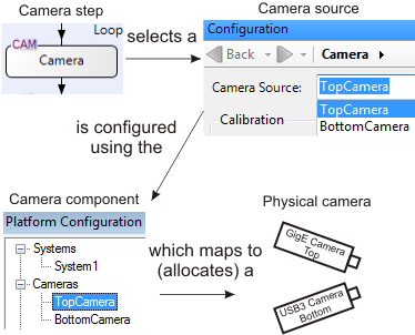
By default, a new project set to run on a PC runtime platform will try to allocate a camera of the type specified when the project is created. If you have a single dedicated camera on your network, then no special action is required for allocation. When there are multiple physical cameras on your network, but only a single camera component in your project, you must select which physical camera to allocate to your camera component. For more information, see the Identifying cameras and changing the default allocation mode subsection of this section.
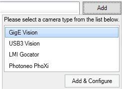
If you want to use multiple cameras in your project or you want to add a third-party sensor, you can add these components using the Platform Configuration dialog. To add a camera component, click on the Add button in the Cameras page of the Platform Configuration dialog, and then select the supported camera or third-party sensor from the presented dialog. Click Add & Configure to specify configuration settings. Any previously added cameras will remain available.
It is recommended to test a new GigE/USB3 Vision camera using Matrox Capture Assistant, discussed below, before connecting to Matrox Design Assistant. In Matrox Capture Assistant, you can more easily diagnose and troubleshoot grabbing or connectivity issues.
Matrox Capture
Assistant
Using
the existing Matrox Design Assistant templates and example
projects
Using external defaults in
your project
On the PhysicalCameraN page of the Platform Configuration dialog, little square markers indicate values that are stored in the runtime platform's registry. These are default values established outside of Matrox Design Assistant using the MILConfig utility.
It is strongly recommended to choose settings not marked with the little square. When you choose an unmarked option, your choice is saved in the Matrox Design Assistant project file. This keeps important settings tied to the project itself, rather than to external defaults. For example, the camera Allocation Mode is best set to the unmarked Camera Name, IP Address, or Device Number option.
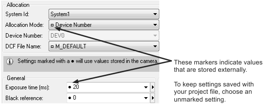
Similarly, some camera settings are stored on the physical
camera itself. A small black dot beside a setting on the
PhysicalCameraN
page indicates that the project will use the value stored on the
camera. Again, it is recommended to set values without the dot.
This ensures predictable project performance, even if you swap out
a camera. For example, if you want to disable triggering for the
camera, and ensure the setting is saved with your project, set the
Trigger input to
 instead of
  .
.
For more information on configuring a GigE/USB3 Vision camera (which can, for example, have additional features not listed in the Platform Configuration dialog), see the Platform settings for your camera section in Chapter 28: Acquisition.