Platform settings for your camera
During design-time (especially when adding a camera to a new project or configuring an older project to work with your camera), use the PhysicalCameraN page of the Platform Configuration dialog, to configure your camera's settings.
To change camera settings during runtime (for example, to disable a hardware trigger when entering a diagnostic or training mode), use platform configuration binding or the CameraSettings step. Alternatively, link a Button element in the operator view to the Change Camera Settings action.
You can access the PhysicalCameraN page through
the
Configure platform ( ) toolbar button in the
Platform toolbar.
) toolbar button in the
Platform toolbar.
 Camera defaults
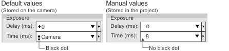
Within the PhysicalCameraN page of the Platform Configuration dialog, camera input values with a black dot to their left indicate that these values are retrieved directly from the camera, and not stored in your project. You can modify these camera settings using the MILConfig utility. Black dot values are especially useful when your project has to run with many different cameras without changing the Matrox Design Assistant project, or when you would prefer to use a specific Matrox Digitizer Configuration File (.dcf) to specify settings.
To save your camera's inputs in your project file, change the value in the dropdown list. This will remove the black dot from the dropdown list, which indicates that the information is not stored on the camera and is instead saved to your project. For example:
PhysicalCameraN
page on the Platform Configuration dialog
The inputs on your PhysicalCameraN page will vary slightly depending on the type of camera being used by your project. For information about the PhysicalCameraN page for Matrox Iris GTR, see the Platform settings for your camera subsection of the Connecting to your Matrox Iris GTR as your runtime platform section in Appendix D: Matrox Iris GTR.
The following is the PhysicalCameraN page of the Platform Configuration dialog for a PC platform in emulation mode. In emulation mode, you can change the settings, but Matrox Design Assistant doesn't know the values that are inquired from the camera, so such settings are shown as being set to Camera.
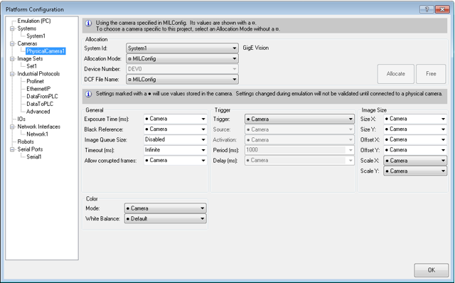
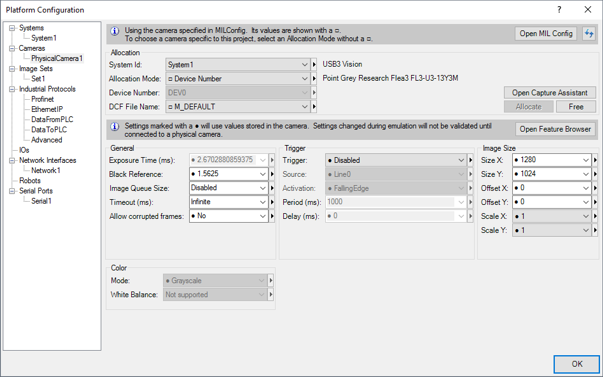
If you switch to a remote platform or a local platform, the values previously shown as set to Camera will have actual values that were inquired from the camera.
Changing the
camera's inputs
The PhysicalCameraN page of the Platform Configuration dialog is divided into several sections:
|
Section name |
Description |
|
|
Open MILConfig Utility |
Allows direct access to the MILConfig utility on the development computer. |
|
|
Allocation |
Identifies your project's camera (and system). Note that each camera added to the Platform Configuration dialog must be associated with a system of the same type. In addition, this section allows you direct access to Matrox Capture Assistant. |
|
|
General |
Identifies your camera's general settings. Note that, in emulation mode, some inputs will be unavailable, but many more will be set to Camera. Names of camera inputs can differ between different supported GigE Vision/USB3 Vision cameras and supported Matrox smart cameras. |
|
|
Input |
Description |
|
|
Exposure Time |
Specifies the length of the exposure, in msec. |
|
|
Black Reference |
Sets the offset of the black level of the image. A low black offset will give a brighter image, while a higher black offset will give a darker image. |
|
|
ImageQueueSize |
Specifies how large your image queue is. See the Continuous grab mode with image queues subsection of the Grab timing section earlier in this chapter for more information. |
|
|
Timeout |
Specifies the time in msec to wait in the Camera step for a trigger before aborting the grab. For more information, see Handling other requests while waiting for a trigger. |
|
|
Trigger |
Specifies whether triggered grab mode is enabled in your project. For more information on triggering possibilities, see the Triggering section earlier in this chapter. |
|
|
Image Size |
Specifies to reduce the image size or change the portion of the image that is scanned during each grab. This is useful if you need to decrease the grab and/or processing time. To adjust (scale) the image size, specify the ScaleX and ScaleY inputs before grabbing an image. Note that you cannot scale an image loaded from disk. To scan only a portion of the entire scannable area, specify values for the Size X, Size Y, Offset X, and Offset Y inputs. Size X and Size Y inputs specify the X and Y dimensions of the scannable area, respectively. The Offset X and Offset Y inputs specify the X and Y offsets of the scannable area from the top-left corner. 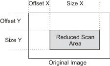
|
|
|
Color |
Specifies color settings applied directly to the data coming from the image sensor; they are therefore only used when using camera images and not when using image sets. For more information on the color mode (color or grayscale), see the Dealing with color images section in Chapter 2: Building a project. For more information on white balance, see the White balance overview section in Chapter 31: White balance. |
|
Note that initial camera settings can be altered through platform configuration binding or using the CameraSettings step's inputs. However, if you try to retrieve a camera input that is set to Camera, it will return the string Unchanged instead of the camera's default value.