
Triggering
Your project can acquire images (grab) either upon reception of a trigger or continuously. When your flowchart reaches a Camera step, the acquired image becomes available to your flowchart.
Continuous grab mode is convenient at runtime for focusing your camera and setting up lighting when testing or demonstrating a project. Typically, however, you will need to trigger your camera(s) explicitly. In this case, the Camera step receives the image only after receiving a trigger and your project operates in triggered grab mode.
There are several ways to configure the trigger for image acquisition when in triggered grab mode. Triggered grab mode has a positive impact on grab timing. See the Grab timing section later in this chapter.
-
Triggering from a hardware signal. The grab starts upon a specified transition of an auxiliary input signal (line).
-
Triggering from a software trigger. The grab starts upon a Trigger step or when clicking a button in the operator view that performs a Send software trigger action. With a software trigger, you can either acquire a new image or reuse the current image.
-
Triggering from a periodic trigger. The grab starts after a specified amount of time, determined using an internal clock. Periodic triggers are generally used for testing or demonstration purposes.
-
Triggering from a PLC with Quick Comm. The grab starts when the PLC changes a specific Quick Comm data field.
-
Triggering from a PLC without Quick Comm. The grab starts when your project detects a PLC acquisition start request using polling (for example, using a ModbusReader step) and triggers the acquisition.
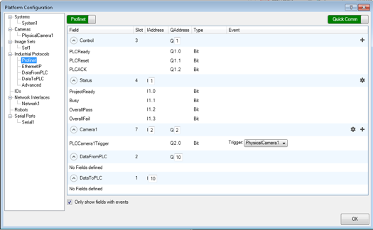
Use the PhysicalCameraN page of the Platform Configuration dialog to configure the trigger settings.
 Common trigger
settings
Common trigger
settings
Triggering
from a hardware signal
Triggering from a software
trigger
Triggering image acquisition from a software trigger is typically the default way to acquire an image in emulation mode and/or when not in a high speed application. There are 3 types of software triggers: a trigger button element in the operator view, a Trigger step, or a PLC trigger with Quick Comm (PROFINET or EtherNet/IP).
Note that you can also use a software trigger with image sets. For more information, see the Procedure for configuring image sets section in Chapter 29: Acquisition using image sets.
To configure your project at runtime (for example, change its trigger source), bind input elements directly to platform configuration settings, use a CameraSettings step in the main or a subflowchart, or link a Button element in the operator view to the Change Camera Settings action.
Procedure for
using the Trigger step to initiate a grab
Using a PLC
trigger with Quick Comm (EtherNet/IP or PROFINET)
Triggering image acquisition using a PLC trigger with Quick Comm allows up to 8 cameras to receive software triggers from external devices using the PROFINET or EtherNet/IP protocol. To use a PLC trigger with Quick Comm:
-
Setup your runtime platform and project to communicate with a PLC using the PROFINET or EtherNet/IP protocol with Quick Comm. For more information, see the Set Quick Comm to trigger acquisition automatically subsection of the Procedure for communicating with controllers section in Chapter 41: Quick Comm protocol and PROFINET and EtherNet/IP steps.
-
On the EthernetIP or Profinet page of the Platform Configuration dialog, enable the PLCCameraNTrigger data field by setting its Trigger event to trigger PhysicalCameraN. This associates the physical camera with the PLC trigger.
-
On the PhysicalCameraN page of the Platform Configuration dialog, set the Camera step to software triggered mode by enabling the Trigger input and setting its Trigger Source input to Software.
Using a
PLC trigger without Quick Comm
Triggering image acquisition from a PLC trigger (triggering from the network) without Quick Comm does not use a hardware trigger, a software trigger, or an image queue. Instead, when your project detects a PLC acquisition start request using polling (for example, using a ModbusReader step), it should trigger the acquisition. So, the Trigger input and the Image Queue Size input, both found on your physical camera's page of the Platform Configuration dialog, must be disabled.
To detect a PLC trigger without Quick Comm, you poll for a signal from your PLC. Since it is not efficient to poll the communication step faster than the scan time of the controller, you should place a Halt step and set the Wait input to the required amount of time.
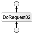
In the following illustration, the AnyReader step could be an EthernetIPReader step, ProfinetReader step, or ModbusReader step.
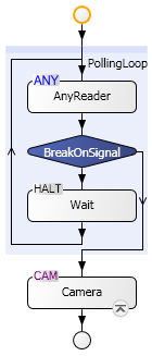
This frees the CPU from busy-waiting for a signal that won't arrive. For developers familiar with Visual Basic, this is similar to using a DoEvents statement. The Camera step should immediately follow the signal loop break. This ensures the smallest time between the signal being received, and grabbing the image.
Triggering from a periodic
trigger
Handling other
requests while waiting for a trigger
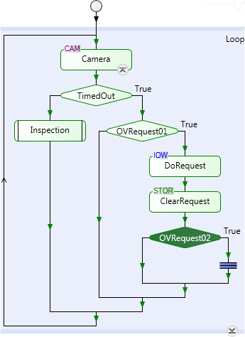
When in triggered grab mode, the Camera step takes an image from the image queue. If the queue is empty, the flowchart will wait at the Camera step until a trigger is received and an image is grabbed. If the trigger takes a long time to arrive, you can process other requests while waiting, by creating subflowcharts for the other processes and initiating them from an operator view event. While the Camera step is waiting for a trigger, the project can still handle events arising from operator view interactions or Quick Comm PLC events, using a subflowchart.
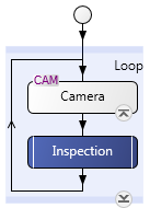
In the above flowchart, if an event from the operator view occurs between the Camera and inspection steps, the inspection process is performed before the event is handled. If, however, the event occurs while the camera is waiting for the trigger, the request is performed immediately. Once the event-triggered subflowchart is finished, control returns to the waiting Camera step.
Although less efficient, you can automatically have the Camera step timeout, perform other processing, and then return back to wait for the trigger. To do so, set the Timeout input (in msec) on the PhysicalCameraN page of the Platform Configuration dialog. If not set, the timeout value is assumed to be infinite (that is, the Camera step will never timeout). The timeout value must be at least twice the Exposure time value. You can then create a loop in your flowchart based on a timeout expression in a Condition step.
Note that if the Camera step times out and it does not grab an image, all subsequent steps that use Camera.Image or Camera.CorrectedImage cannot run. Also, in the operator view, any data in the same publishing group as a display linked to Camera.Image or Camera.CorrectedImage will not be published. To prevent this, precede the steps that rely on the Camera step with a Condition step so you do not proceed to these steps if the camera has timed out. .