
Procedure for communicating with Modbus
The following steps provide a basic methodology for communicating with Modbus in Matrox Design Assistant:
-
Use the MILConfig utility to configure the Modbus protocol instance on the runtime platform.
-
In Matrox Design Assistant, in the Platform Configuration dialog, select and enable the relevant Modbus protocol instance for your project.
-
Read data using the ModbusReader step.
-
Perform some analysis and calculate new data to write back to the PLC.
-
Write data using the ModbusWriter step.
For information about running multiple projects simultaneously, and the restrictions for projects that use industrial protocols, see the Communication protocols subsection of the Considerations when running multiple projects simultaneously section in Chapter 60: Running multiple projects on a runtime platform.
 Setting up communication
with Modbus
Setting up communication
with Modbus
Before you can communicate with a PLC using the Modbus protocol, you must set up the communication environment on the PLC's side (using a third-party configuration software package) and on the runtime platform's side (using the MILConfig utility). Then, you can enable the Modbus protocol for your project in Matrox Design Assistant.
Configuring the
PLC
Configuring the runtime
platform
To run the Modbus protocol on your runtime platform, launch the MIL Control Center, open the MILConfig utility, expand Communication, select Modbus, and add or remove Modbus protocol instances (instance names are case sensitive).
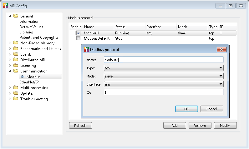
You must then select the communication type of the Modbus protocol. In addition, you must set the mode in which the runtime platform should act: slave mode or master mode. In slave mode, to send data to the PLC, the runtime platform writes to its own data tables in local memory and the PLC will read from these data tables in its next read cycle; whereas, to receive data from the PLC, the runtime platform reads from its own data tables the data written by the PLC during its previous write cycle. In master mode, the runtime platform reads from/writes to the data tables of slave automation devices.
If you set your runtime platform to slave mode (regardless of the communication type), set the ID field to the user-defined identifier that you associated with the runtime platform when configuring the PLC.
When entering a value for the ID field, be aware that 0 is a reserved value and valid values start at 1.
For a TCP communication type, if your runtime platform has multiple network adapters and is set to slave mode, set the Interface dropdown list to the network adapter that the runtime platform should listen to for incoming requests from the master. If set to any, the runtime platform will listen to all its network adapters for requests from the master; this is not very efficient. If the runtime platform is set to master mode, you should specify all the devices on the Modbus network in the MILConfig utility; for better performance specify their slave IDs and their IP addresses. If your runtime platform has multiple network adapters, the operating system will select the most appropriate network adapter, based on the adapter's subnet address and the IP address of the slave device to which a request is sent.
For an ASCII or RTU communication type, you must also configure the following settings:
-
Port. This is the serial port on the runtime platform with which to communicate (COM port).
-
Baud Rate. This is the speed at which data is transferred per second; it is not necessarily the same as the bit rate.
-
Parity. A parity bit is an extra data bit (0 or 1) that is added to each character for error checking purposes. The possible values for parity are:
-
None. This means that there is no parity bit being sent.
-
Odd. Specifies that the parity bit being sent ensures that the number of 1's is odd. For example, if there is an odd number of 1's, the parity bit will be set to 0.
-
Even. Specifies that the parity bit being sent ensures that the number of 1's is even. For example, if there is an even number of 1's, the parity bit will be set to 0.
-
-
Stop bits. A stop bit is an extra data bit that is added to each character to indicate the end of the character. There can be 1 or 2 stop bits at the end of a character.
-
COM Type. This is the serial communication standard which will be used (RS-232 or RS-485).
Enabling Modbus
in the Platform Configuration pane
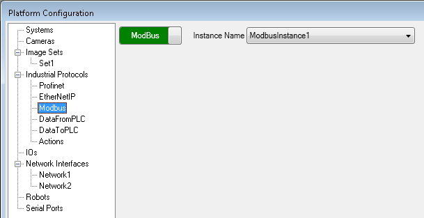
Once you have configured the specific Modbus protocol instance for your platform, you must enable the protocol for your project. By default, the Modbus protocol is disabled for a Matrox Design Assistant project. You can enable it by opening the Platform Configuration dialog, and navigating to the Modbus page under the Industrial Protocols page. Make sure to verify the instance name and select it from the list, then click on the slider to enable the protocol.
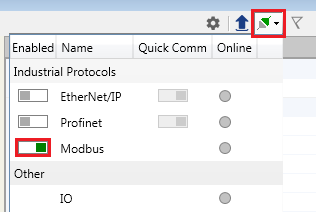
Alternatively, you can enable it in the Communications dropdown panel, accessible from the Matrox Design Assistant Platform toolbar. However, you cannot select a different Modbus instance this way.
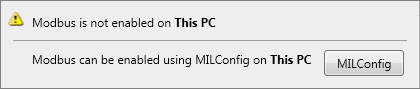
If you enable the Modbus protocol for your project before configuring the Modbus protocol service for your platform (in the MILConfig utility), a warning sign will appear. When you click on it, a dialog will appear, as shown below. If you are connected to a local runtime platform, you will be able to click on the MILConfig utility button and configure the Modbus protocol service in the MILConfig utility. If you are using a remote runtime platform, you must first connect to it remotely, open the MILConfig utility, and configure the Modbus protocol service.
Note that, unlike all other communication types supported by Matrox Design Assistant, the Modbus protocol is not configured in the Platform Configuration dialog.
Using the
ModbusReader step
The ModbusReader step allows you to read from Modbus data tables. When the runtime platform is in slave mode, the step can read from any of the 4 Modbus data tables in local memory. However, since the PLC can only write to the runtime platform's coil and holding register data tables, you should expect to receive new data in these 2 data tables. When the runtime platform is in master mode, the ModbusReader step can read from any of the slave automation device's 4 Modbus data tables.
Note that to read the data tables of a remote slave device, it is necessary to specify the IP address of the remote slave device using IPv4 dotted-decimal notation (for example, 192.168.52.141).
The following steps provide a basic methodology for using the ModbusReader step:
-
Add a ModbusReader step to the flowchart.
-
In the Configuration pane, choose the Target device from which to read. Select Local device to read from the runtime platform's data tables, or Remote slave to read from a slave device's data tables.
To read from a slave device, your runtime platform must be set to master mode (in the MILConfig utility), and you must specify the remote slave's IP address and ID (Node address) in the step's Configuration pane. If you have listed all the slave devices on the Modbus network in the MILConfig utility (as described earlier in this section), you can avoid configuring the ModbusReader step with an explicit IP address and re-establishing a connection with the slave device each time the step is run. In this case, you must specify only the slave device's ID and enable the Use persistent connection option; the step will use the ID to determine the IP address of the slave device, and a connection with the device will be established only once, when you boot the runtime platform. This allows for better performance, but blocks other Modbus masters from connecting.
-
In the Configuration pane, click on the Add button to add an entry (data field) to the ModbusReader step. One or more entries can be added to the step.
-
Assign the entry a meaningful name and specify its Data type, as well as specify the data table (Table) from which to read the entry. Depending on the selected data table, you will need to specify a Coil number, a Register number, or a Discrete input number. These Modbus fields are further explained in the Modbus data configuration section later in this chapter .
Note that each time an entry is added, its coil, register, or discrete input number will be set to 1 by default. You are responsible for changing this number, to ensure that there are no conflicts or duplications of every coil, discrete input, input register, and holding register number specified for the different entries and steps. Also, the data read will be invalid if the number and data type specified for an entry (data field) overlaps the memory used by another entry.
-
Once you have added an entry, you can rename it or delete it, or you can add another entry. You can also duplicate it, which adds the duplicated entry to the Read entries list. If you click on an entry, you can view information about it and make the following changes:
-
If you added an entry to the coil or discrete input register, you can change its Coil number or Discrete input number, respectively. These numbers can be between 1 and 128.
-
If you added an entry to an input register or a holding register, you can change its Register number. The Register number can be between 1 and 128.
-
When receiving a trigger from a Modbus device, it is recommended to avoid busy waiting (that is, repeatedly checking the ModbusReader step's value without a delay). The recommended approach consists of creating a polling loop, and is described in the Triggering section in Chapter 28: Acquisition.
For more information on configuring Modbus data fields, see the Modbus data configuration section later in this chapter.
Accessing
ModbusReader results
The ModbusReader step results are organized per entry. The diagram below displays an example of a ModbusReader step and its entries.
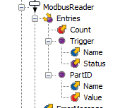
The condition expression ModbusReader.Entries("Trigger").Status = On will be true when the PLC sets the trigger bit. In Matrox Design Assistant, you should use the named constants On / Off, rather than guessing their numeric equivalent.