Modbus steps overview
 Previous
- Next

The Modbus steps allow you to communicate information, using the Modbus communication protocol, between your runtime platform and other Modbus devices, such as a programmable logic controller (PLC), expansion I/O modules, or a robot controller. Modbus is an industrial communication standard for connecting devices together, and it defines a communication protocol that allows interaction between devices used in industrial automation processes. The information is received or transmitted through the runtime platform's 100 Mbit/1 Gbit Ethernet port, or serial port (COM port).
There are 3 Modbus protocol types that are supported in Matrox Design Assistant (if provided by the runtime platform hardware) and that Matrox Design Assistant can be Modbus master to:
-
Modbus TCP, which uses the 100 Mbit/1 Gbit Ethernet port.
-
Modbus RTU, which uses the serial port.
-
Modbus ASCII, which also uses the serial port.
On the runtime platform, enable and configure Modbus communication using the MILConfig utility. You can configure your runtime platform as either a slave device or a master device. Typically, the runtime platform is configured as a slave device, but when communicating with some external I/O modules and robot controllers that are themselves slave devices, it is necessary to configure the runtime platform as a master device. If Modbus is already enabled in the MILConfig utility communication page, you can also use the Matrox Design Assistant portal page to configure this protocol. For more information see Portal pages for monitoring communication.
Once communication has been configured in the MILConfig utility, you can communicate with a PLC (or other device) using the ModbusWriter step and the ModbusReader step. The ModbusWriter step allows you write to Modbus data tables, and the ModbusReader step allows you read from Modbus data tables.
 Modbus data
tables
Modbus data
tables
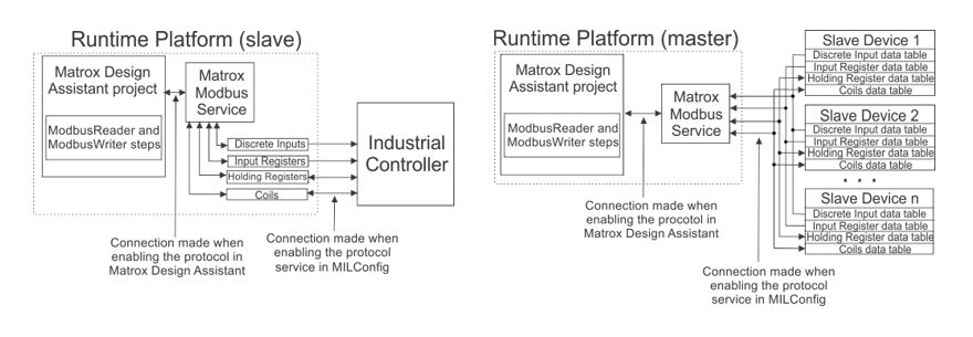
Each Modbus slave device has a block of memory that is divided into 4 local data tables to be used by Modbus. When the runtime platform is set to slave mode, Modbus data tables are created in its local memory. In this mode, to send data to the PLC, the runtime platform writes to its own data tables in local memory and the PLC (or master) will read from these data tables in its next read cycle; whereas, to receive data from the PLC, the runtime platform reads from its own data tables the data written by the PLC during its previous write cycle. If the runtime platform is set to master mode, it reads from and writes to the data tables of slave devices. When reading from or writing to a device, you must specify the data table to use. The 4 data tables are:
|
Data table name |
Runtime platform as slave |
Runtime platform as master |
Type of data |
||||
|
Read from local |
Write to local |
Read from slave |
Write to slave |
Read Function code |
Write Function code |
||
|
Coil |
Yes |
Yes |
Yes |
Yes |
01 |
15 |
Used for up to 128 single bits of data. |
|
Holding registers |
Yes |
Yes |
Yes |
Yes |
03 |
16 |
Used for up to 128 16-bit blocks of data (registers). These can be combined and configured to accept a combination of data of various types (such as, short, integer, float, to name a few) |
|
Discrete inputs |
Yes |
Yes |
Yes |
No |
02 |
N/A |
Used for up to 128 single bits of data. |
|
Input registers |
Yes |
Yes |
Yes |
No |
04 |
N/A |
Used for up to 128 16-bit blocks of data (registers). These can be combined and configured to accept a combination of data of various types (such as, short, integer, float, to name a few) |
The diagrams below display how Modbus data tables are used when the runtime platform is set to slave mode and master mode, respectively.