Considerations when running multiple projects simultaneously
When running multiple projects simultaneously on a runtime platform, you must explicitly divide its resources, if they are needed by more than 1 of the projects. Any conflict, such as multiple projects trying to use the same camera to grab images, is reported and must be resolved.
To prevent such conflicts, do not use default values for hardware related settings that are used by multiple running projects; instead, explicitly specify these settings so that each project uses a specific and different resource. For example, you must explicitly specify settings for:
-
Auxiliary I/O signals and related resources (such as rotary decoders and timers on the Matrox Advanced I/O Engine).
The maximum number of projects that you can run simultaneously on a runtime platform depends on its resources, and the resources required by the projects. For example, simultaneously running 2 projects that use a rotary decoder requires a runtime platform with at least 2 rotary decoders.
 Camera
allocation
Camera
allocation
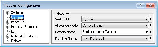
To simultaneously run multiple projects that grab from a camera, the camera allocation mode must be set, for each project, to a specific and different camera (for example, a specific and different IP address or camera name). To confirm this, use the Cameras page of the Platform Configuration dialog.
For more information, see the Cameras and your runtime platform section in Chapter 2: Building a project.
Templates
and example projects
Auxiliary I/O signals
and related resources
To simultaneously run multiple projects that use auxiliary input and output signals, you must explicitly specify the I/O related settings, which you can access from the IOs page of the Platform Configuration dialog.
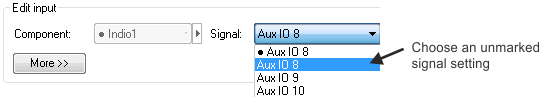
When specifying an auxiliary input or output signal on the IOs page, you must choose an unmarked signal (no black dot) from the Signal dropdown list. Otherwise, starting another runtime project will report an error. Choosing an unmarked (non-default) signal ensures that the setting is stored with the project.
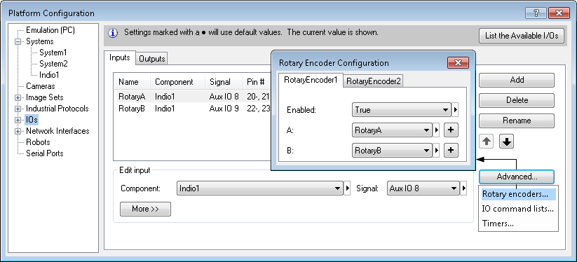
I/O related settings that you must explicitly specify also include those for rotary decoders, timers, delays, and I/O command lists. For example, if you are running multiple projects that use a rotary decoder, you must set a specific and different one for each project, using the Rotary Encoder Configuration dialog, accessible by clicking on the Advanced button in the IOs page.
For more information, see the Matrox Advanced I/O Engine section in Chapter 40: IO steps.
Typical I/O
tasks
Using
platform I/Os to synchronize capture and reference stamps
If you enable the Use platform I/O(s) to synchronize capture and reference stamps checkbox on the Cameras page of the Platform Configuration dialog, a diagram is displayed, showing the input and output pins and command lists used by the project. For every simultaneously running project that uses these resources, you must explicitly specify specific and different settings. The following example shows the respective diagrams for 2 projects, each of which uses different pins and command lists.
Diagram for the first project:
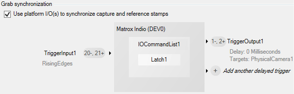
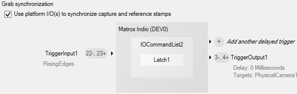
Diagram for the second project:
For more information, see the Grab synchronization with a reference stamp subsection of the Matrox Advanced I/O Engine section in Chapter 40: IO steps, the Synchronizing across multiple Matrox Indio boards subsection of the Matrox Indio Advanced I/O Engine section in Appendix E: Matrox Indio, and the Using multiple cameras section in Chapter 28: Acquisition.
Communication
protocols
Matrox Design Assistant supports communication with PLCs using the PROFINET, EtherNet/IP, and Modbus industrial protocols. It also supports communication with industrial robot controllers and with external hardware devices via serial port connection and TCP and UDP networking protocols. Related communication settings must be set explicitly, when multiple running projects are using such resources.
It is strongly recommended that you view the video tutorial on industrial communication, available in the Quick Start tab. Matrox Vision Academy provides further video tutorials on industrial communication, available to registered users at https://www.matrox.com/imaging/vision_academy/.
Instances of the protocol
service
Every runtime project maintains its own connection to an instance of the industrial protocol service.
Every project that is running simultaneously, and uses industrial protocols, must have its own unique instance of the protocol service enabled. To enable or disable the protocol service, as well as create, configure, and name instances (which are case sensitive), use the Communications page in the MilConfig utility on the runtime platform (with a Matrox Iris GTR, this can be done from the COMMUNICATION portal pages).
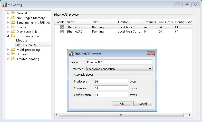
Each instance of the protocol service has its own data tables and an interface setting that indicates the NIC or serial port (depending on the protocol) on which to communicate. Typically, each instance should use its own separate and unique network interface (NIC) or serial port. Note that some NICs have several interfaces (for example, Matrox Concord PoE).
In general, every running project that uses industrial protocols should have its own physical NIC (NICs cannot usually be shared among these running projects). When using the EtherNet/IP and Modbus industrial protocols, it can be possible to use virtual NICs (virtual interfaces), with Microsoft Windows 10. In this case, you can create multiple virtual NICs on 1 physical NIC. You can then use a virtual NIC when specifying the interface for your instance. Note that, once you use the physical interface for an instance, you cannot then create virtual interfaces on that NIC.
Virtual NICs are never possible when using the PROFINET industrial protocol. Every running project that uses the PROFINET protocol requires its own physical NIC with the Matrox PROFINET Engine (for example, Matrox Indio).
For information about configuring multiple physical NICs or multiple virtual NICs, refer to the Matrox Design Assistant Readme. For information about adding, configuring, and deleting instances of the protocol service, see the Enabling the PROFINET and EtherNet/IP protocol service subsection of the Procedure for communicating with controllers section in Chapter 41: Quick Comm protocol and PROFINET and EtherNet/IP steps.
Example of
multiple projects communicating with a PLC
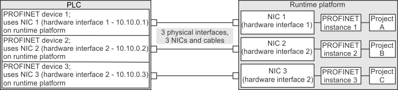
The following is an example of multiple running projects communicating with a PLC using multiple PROFINET instances. For each of the 3 running projects in this example (Project A, B, and C), a separate and unique instance was created using a separate and unique interface (3 physical NICs). Each interface (NIC) must have the Matrox PROFINET Engine (for example, 3 Matrox Indios).
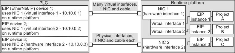
The following is an example of multiple running projects communicating with a PLC using multiple EtherNet/IP (EIP) instances. For each of the 3 running projects in this example (Project A, B, and C), a separate and unique instance was created using a separate and unique interface (NIC). The first 2 instances were created using virtual interfaces on the first physical NIC. The third instance was created directly on the second physical NIC.