Matrox Indio Advanced I/O Engine
 Previous
- Next

Matrox Indio has an Advanced I/O Engine. The engine has 8 auxiliary input signals, 8 auxiliary output signals, 2 rotary decoders, 2 I/O command lists (with 4 reference latches), and 16 timers. For more information, see the Matrox Advanced I/O Engine section in Chapter 40: IO steps.
 Synchronizing
across multiple Matrox Indio boards
Synchronizing
across multiple Matrox Indio boards
Single
camera example with synchronized Matrox Indio boards
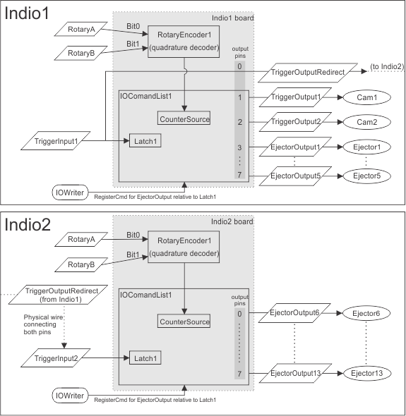
In this first example, there are 2 connected Matrox Indio boards (Indio1 and Indio2) that share one camera. The trigger input signals on both Matrox Indio boards must be synchronized so that the ejectors all fire relative to the same reference. For this setup, you will first need to:
-
Add 2 Matrox Indio systems. See the Adding a Matrox Indio system to your project section earlier in this chapter.
-
Enable the Use platform I/O(s) to synchronize capture and reference stamps checkbox (in the Cameras page of the Platform Configuration dialog). This will add TriggerInput1 and TriggerOutput1 to the Indio1 system component.
-
Optionally, add and connect the input signals (pins) receiving input from a quadrature encoder (RotaryA and RotaryB) to Indio1, so that you can specify delays in terms of displacement along the conveyor belt.
-
Add a new output to redirect the trigger input signal. To do so, in the IOs page of the Platform Configuration dialog, click on the Add button in the Outputs tab. In the Edit output section, select Input from the Source type dropdown list and TriggerInput1 from the Input dropdown list. Set the Delay to 0.
-
Optionally, click on the Rename button to change the output's name. In the example diagram, this output is labeled TriggerOutputRedirect.
Note that you might need to close and reopen the Platform Configuration dialog to update the names in the Inputs tab and Outputs tab.
-
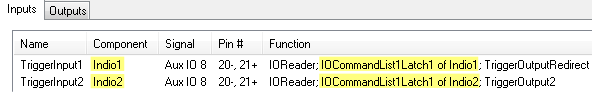
Add a new input on Indio2. To do so, click on the Add button in the Inputs tab (found on the IOs page of the Platform Configuration dialog). Choose Indio2 from the Component dropdown list; then, choose the Create a delayed pulse on output option, and click on the Add & Configure button. In the example diagram, this input is labeled TriggerInput2.
-
Click on the Advanced button and choose IO command lists...; then, choose the board and latch.
-
Physically connect the 2 Matrox Indio boards. Connect a wire from the TriggerOutputRedirect pin on Indio1 to the TriggerInput2 pin on Indio2.
-
If you added rotary encoder signals in step 3 above, do the same for Indio2. Connect the same A and B signals from the rotary encoder to the inputs of Indio2.
Note that each Matrox Indio board has 2 available command lists: IOCommandList1 and IOCommandList2. You must configure all trigger or ejector output signals to use the same numbered command list on each board. For example, if you configure to use IOCommandList1 on the first board, configure trigger/ejector signals to use IOCommandList1 on all subsequent synchronized boards.
Similarly, for trigger input signals, you must configure the I/O command list to use the same numbered latch. For example, if Latch1 of IOCommandList1 is specified for TriggerInput1 on the first Matrox Indio board, you must specify Latch1 of IOCommandList1 for the trigger input signals of subsequent synchronized boards.
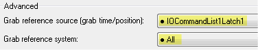
In the Platform Configuration dialog's PhysicalCameraN page, verify that the Grab reference source accurately reflects the command lists and latches specified on the IOs page, and that the Grab reference system is set to All. When All is specified, Matrox Design Assistant will automatically choose the reference value from the right board.
The following illustration shows the setup for one camera with multiple Matrox Indio boards.
Multiple
camera example with synchronized Matrox Indio boards
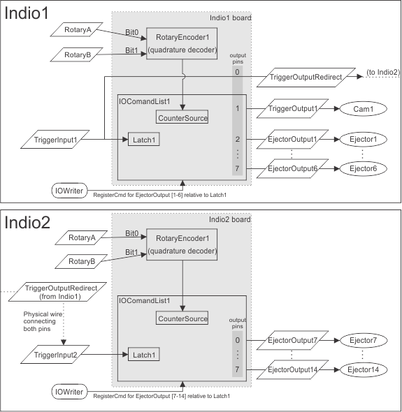
The following illustration shows the setup if you need to use more than one camera and ejector outputs with multiple Matrox Indio boards. The setup is similar to the first example.
Note that it is best to connect all cameras to the first Matrox Indio board.
To set up the first camera (connected to TriggerOutput1 on Indio1) and all ejector output signals, follow the procedure described in the Single camera example with synchronized Matrox Indio boards subsection of this section. To trigger any additional cameras using the output signals from the first board (Indio1), see the Grabbing with the Matrox Advanced I/O Engine subsection of the Using multiple cameras section in Chapter 28: Acquisition.