
Using multiple cameras
 Previous
- Next

You can have a project that uses multiple cameras on a PC runtime platform. Each physical camera used by the project is associated with its own image queue, allowing acquisitions to occur simultaneously. However, processing is typically done sequentially. For more information, see the Multi-buffering with image queues subsection of the Grab timing section earlier in this chapter. Typically, projects with multiple cameras acquire multiple images of the same object from different angles or at different points along a conveyor.
There are several ways to configure your project to acquire images from multiple cameras:
-
If triggering from a PLC with Quick Comm, the PLC can trigger up to 8 cameras. See the Set Quick Comm to trigger acquisition automatically subsection of the Procedure for communicating with controllers section in Chapter 41: Quick Comm protocol and PROFINET and EtherNet/IP steps.
-
If triggering from a PLC without Quick Comm, or using a message from the SerialPortReader step or NetworkReader step, to initiate the grab, see the Grabbing multiple images using a PLC trigger without Quick Comm subsection of this section.
-
If triggering from an auxiliary input signal (discrete input) with the Matrox Advanced I/O Engine, see the Grabbing with the Matrox Advanced I/O Engine subsection of this section. Triggering multiple cameras with an auxiliary input signal is best managed with the Matrox Advanced I/O Engine (such as, on a Matrox 4Sight GPm).
-
If triggering from an auxiliary input signal (discrete input) without the Matrox Advanced I/O Engine (such as, when using a non-Matrox PC platform), see the Grabbing without the Matrox Advanced I/O Engine subsection of this section.
You can potentially design and simplify certain applications that require multiple cameras using multiple independent projects, and then run the projects simultaneously. For more information, see the Multiple cameras subsection of the Developing multiple projects to run simultaneously section in Chapter 60: Running multiple projects on a runtime platform.
 Grabbing with the
Matrox Advanced I/O Engine
Grabbing with the
Matrox Advanced I/O Engine
When using multiple cameras, the grab synchronization feature of the Matrox Advanced I/O Engine ensures that the images at the head of image queues have been grabbed from different cameras originating from the same initial trigger input, although they might have different specified delays; the images will receive the same timestamp. For example, if you have a multi-camera setup and your production line cannot be stopped during camera initialization, grab synchronization enables each camera's grab to belong to the same trigger.
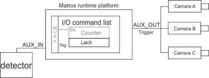
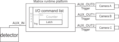
To use the grab synchronization feature, connect the trigger signal to an auxiliary input signal of the Matrox Advanced I/O Engine and connect an auxiliary output signal(s) of the Matrox Advanced I/O Engine to the trigger input of the cameras. If all the cameras are to be triggered at the same time, use a single auxiliary output. Use multiple auxiliary output signals if a single hardware trigger will generate a series of camera triggers, each with a different delay.
If Matrox Design Assistant detects a de-synchronization, the image queues are cleared and the process is reset so that grabbed images are again synchronized to the input trigger.
Simultaneous
grabbing
Matrox Design Assistant can trigger the cameras, attached as follows, to grab at the same instant (simultaneous grabbing).
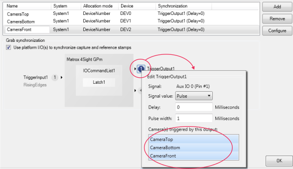
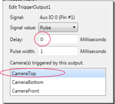
To configure a simultaneous grab, enable the Use platform I/O(s) to synchronize capture and reference stamps option on the Cameras page of the Platform Configuration dialog. This option allows you to associate an auxiliary input signal (for example, TriggerInput1) with the auxiliary output signal (for example, TriggerOutput1) to send to multiple cameras.
Note that, clicking on the name of the auxiliary output signal (such as, TriggerOutput1) allows you to rename it.
To configure the auxiliary output signal, click on the circled
number ( ). You can now select all the cameras to which
the trigger should be sent. The 3 cameras, renamed in the above
image to match their position relative to the object, will now
receive the same trigger.
). You can now select all the cameras to which
the trigger should be sent. The 3 cameras, renamed in the above
image to match their position relative to the object, will now
receive the same trigger.
The Matrox Advanced I/O Engine can delay the trigger sent to your camera relative to the input signal. The delay can be in milliseconds or rotary decoder transitions (depending on if a rotary decoder has been configured), although in the previous example there is no delay applied.
Staggered
grabbing
To generate staggered output triggers from one input signal, specify individual delays for each auxiliary output signal. Using the Matrox Advanced I/O Engine, you can configure each auxiliary output signal so that it is delayed a specific amount of time or number of rotary decoder transitions relative to the input trigger, before it is sent to the camera as a trigger.
To configure a staggered grab, enable the Use platform I/O(s) to synchronize capture and reference stamps option on the Cameras page of the Platform Configuration dialog. This option allows you to associate an auxiliary input signal with the auxiliary output signals (for example, TriggerOutput1) to send to the different cameras.
To configure an auxiliary output signal, click on the circled
number (). You can now select the camera to which the
trigger should be sent and specify the required delay for this
trigger in milliseconds or rotary decoder positions (depending on
if a rotary decoder has been configured).
For each subsequent camera, click on the circled plus-sign
( ) to specify the delay and select the camera to
affect. When finished, click on the Add button.
) to specify the delay and select the camera to
affect. When finished, click on the Add button.
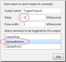
The 3 cameras, renamed in the above image to match their positioning relative to the object, will now receive a trigger delayed by the specified time or transitions.
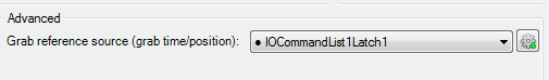
The image timestamp (Camera.GrabTime) or position stamp (Camera.GrabPosition) will be the same for all of the images grabbed upon the same trigger. The Grab reference source input is automatically set to IOCommandList1Latch1 when synchronization is selected.
Grabbing without the
Matrox Advanced I/O Engine
Without access to a Matrox Advanced I/O Engine, connect the hardware trigger(s) directly to the trigger inputs of the cameras. In this configuration, the timestamp (Camera.GrabTime) is the moment at which the PC runtime platform receives the first packet of image data.
If you expect to receive triggers during vision system startup, you should ensure that all the images at the head of the image queues are from the same trigger. To do this, verify that the timestamp of your grabbed images are within a given delta of each other. If an image has a timestamp greater than the delta from the timestamp of the other images, then that image might not have been grabbed upon the same trigger. The images with the oldest timestamps should be discarded, and the process repeated until all the images have a timestamp within the delta.
Grabbing
multiple images using a PLC trigger without Quick Comm
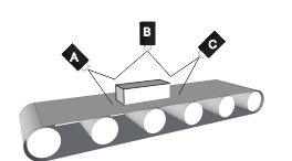
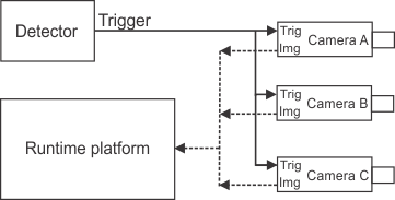
To trigger acquisition from multiple cameras upon a PLC trigger without using Quick Comm (or upon a trigger from the network), set up a wait for trigger loop at the top of the flowchart loop and follow it immediately with a software trigger (Trigger step) for each camera; then, process the images sequentially. This produces the highest throughput. In the following example, 3 sides of an object must be inspected nearly simultaneously: the top, bottom, and the front of the object. The PLC sends a signal, and the flowchart grabs an image from each of 3 physical cameras in a quick burst.
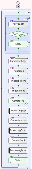


Once all the images are stored in their respective image queues, each image is processed by its own Camera step and processing steps (placed in a subflowchart for this example). Once all the processing is complete, the project waits for the next signal from the PLC to take the next burst of images. For more information, see the Multi-buffering with image queues subsection of the Grab timing section earlier in this chapter.