Cameras and images
Matrox Design Assistant grabs, corrects, processes, and analyzes images, which you can acquire from a camera, a third-party sensor, or an image set. To specify related settings, use the Platform Configuration dialog.
To manage image files, use the Camera Images pane.
 Camera step
There are several sources of images that Matrox Design Assistant can use, but the typical source is the Camera step. The Camera step's main function is to fetch an image and pass it to whichever steps need it. Image data is typically acquired from physical cameras, possibly in response to a trigger. The Camera step will wait until an image is available. The Camera step can also simulate a grab by passing along images from the network or local disk (image set), rather than images from your camera.
Every typical project needs at least one Camera step to work with images, and so, by default, every new project starts with a single Camera step in a loop.
The
Camera step's display view allows you to view the image
being acquired. When acquiring images from a camera, the display
view allows you to adjust the lighting, aperture, and focus of the
physical camera without having to loop through the flowchart. Use
the
Camera Live (![]() ) toolbar button in the
Project toolbar to see the camera's real-time view. Note
that this is only available if triggering is not enabled on the
camera. When the
Camera step is first added to the project, or the project
is first opened and the step has not run, the display view for the
Camera step is blank. To view the image being acquired,
select the
Camera step and click on the green triangle in the display
view, or click on the
Run to selected step (
) toolbar button in the
Project toolbar to see the camera's real-time view. Note
that this is only available if triggering is not enabled on the
camera. When the
Camera step is first added to the project, or the project
is first opened and the step has not run, the display view for the
Camera step is blank. To view the image being acquired,
select the
Camera step and click on the green triangle in the display
view, or click on the
Run to selected step (![]() ) toolbar button in the
Project toolbar.
) toolbar button in the
Project toolbar.
When using a GigE Vision camera or a USB3 Vision camera, your camera must be connected, turned on, and be accessible through your network or directly connected to your runtime platform. It is extremely important that your network be configured appropriately to handle the large volume of data that can be generated by GigE and USB3 cameras. You can use the Matrox Capture Assistant utility to help configure a new GigE or USB3 camera. See the Matrox Capture Assistant subsection of the Cameras and your runtime platform section earlier in this chapter for more information.
The Camera step also provides images of the appropriate bit depth to steps that link to the Camera step. When enabled, the Camera step's remapping settings specify what portion of the input data values to keep, and convert the data to the right bit depth as needed.
The Camera step is discussed in more detail in the the Procedure for using the Camera step section in Chapter 28: Acquisition.
Analysis steps and the image
they use
Analysis and Processing steps, such as the BlobAnalysis step and the SureDotOCR step, usually come after the Camera step, and typically operate on images grabbed using the Camera step.
Some steps, such as the ImageProcessing step, do not only operate on images, but also create images for use by other steps. Consequently, every step that uses an image requires that you select the image on which to operate from the Image property, configurable in the Configuration pane. The format for specifying an image is StepName.ImageName. Keep in mind that some steps can output different images, and so are specified accordingly. For example, the Image property's dropdown list shown below offers 2 separate Camera step images: Camera.Image and Camera.CorrectedImage. The 4 other images in the dropdown list are outputs from separate BlobAnalysis steps.
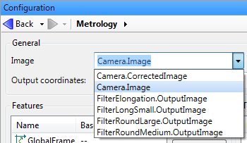
Only select the Camera.CorrectedImage option if the Camera step is associated with a calibration file.
Sometimes, it is useful or necessary to use images stored on disk rather than grabbed from your camera. Typically, disk images are used when you are building or testing a project and you want to use either an ideal image or an image with a known defect. Note that when in emulation mode, you can only use images on disk. For more information on accessing images from disk, see the Procedure for configuring image sets section in Chapter 29: Acquisition using image sets.
You can also use static images, which are taken from the image repository on your runtime platform and are used as master images or templates by some steps. Any step that uses images can use a static image. For more information about static images and the image repository, see the Using static images section in Chapter 35: Static images.
For information on supporting color images, see the Dealing with color images section later in this chapter.
Initial
platform settings
To adjust the various settings required to grab an image, including the triggering options discussed below, use the Platform Configuration dialog. The default settings of the Platform Configuration dialog are sufficient for most projects. In this dialog, you can adjust the exposure and triggering properties, among others. See the Platform settings for your camera section in Chapter 28: Acquisition for information on the various options available.
Often, after testing the initial setup, you want the selected settings to remain unchanged; however, when you require more than one grab configuration (for example, one configuration for training and another for inspecting), it is necessary to make runtime changes. To make camera-related runtime changes, you can bind input elements directly to platform configuration settings or use the CameraSettings step. You can also link a Button element to the Change Camera Settings action. For more information, see the Changing the acquisition settings at runtime section in Chapter 28: Acquisition.
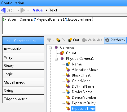
To include any of the platform configuration settings in an expression, you can link to them. For example, to link to the camera's exposure time while working in the operator view, use the Configuration pane to find the setting in the tree structure, and apply the link.
Setting up
your physical camera
You can acquire images in Matrox Design Assistant by attaching a camera to your runtime platform (if not using a smart camera), adding a Camera step to the project, and, if necessary, initializing your camera settings to set the grabbing trigger.
The procedure for configuring a (triggered) grab depends on your hardware configuration. Common setups are described below. Note that the following procedures assume that the correct camera type is already specified and allocated.