
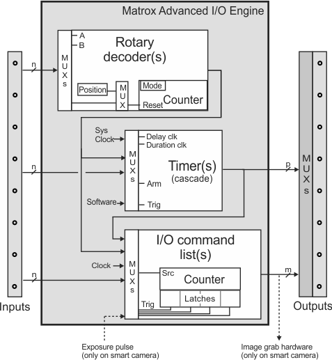
Matrox Advanced I/O Engine
The Matrox Advanced I/O Engine consists of a series of hardware elements that allow you to communicate and coordinate events using I/O pins. These elements are used in more advanced I/O applications. They include:
-
Timers. Timers are used with I/O signals to coordinate events with external devices. For example, when grabbing an image , you can use an auxiliary input signal as a trigger source for a timer, and use an auxiliary output signal to route the timer's output to initiate and set the duration of the camera exposure.
-
I/O command lists. An I/O command list is an internal container for I/O commands. These are commands that can change the state of an output signal at a specified time or counter value. I/O command lists are used to queue and schedule I/O commands.
-
Rotary decoders. Rotary decoders are used to decode input from a rotary encoder. Matrox platforms equipped with the Matrox Advanced I/O Engine have rotary decoders that can decode quadrature input (2-bit Gray code derived from 2 signals) from a rotary encoder. Note that Matrox Design Assistant uses the terms rotary encoder and rotary decoder interchangeably.
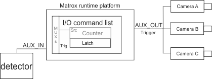
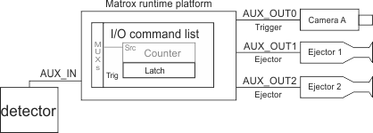
The number of advanced hardware elements available varies depending on the runtime platform. The following diagram displays how these elements are typically organized.
 Timers
Timers are configured using the Platform Configuration dialog. Perform the following steps to set up a timer:
-
Navigate to the IOs page of the Platform Configuration dialog, and add an input and output signal to the project; when adding the input signal, choose the Other option.
-
Click on the Advanced... button and choose the Timers... option from the displayed list (Timer Configuration is presented).
-
Click on the Add button to add a timer.
-
Change the timer's properties to describe the output pulse required for your application. The following are the properties that you can configure for each timer:
Property
Description
Trigger Source
Sets the timer's trigger source. A timer can be triggered by the system clock (Continuous), by any of the active input signals, or by a rotary decoder's output signal. If a timer's source is set to Software, the timer must be triggered by a Trigger step with the timer specified as the target. The Operator View trigger button is able to send a physical trigger, or a trigger to an image set, but it cannot send a Software trigger to a timer. Additionally, a timer can be triggered by the signal generated by another timer.
Trigger Activation
Sets the signal transition or level upon which to trigger the timer. When set to level high or low, the timer can generate multiple consecutive output signals upon a single trigger pulse; essentially, if the trigger signal is still at the specified activation level when the timer finishes outputting a signal, the timer generates another signal.
Output Inverter
Sets whether the output signal should be inverted. This causes the signal to be high during the delay and low during the active period (duration).
Clock Source
Sets the source of the clock that drives the active portion (duration) of the timer's output signal. Depending on the hardware available, this can be either the system clock, so that the timer counts in units of time, or a rotary decoder, so that the timer counts in decoder output signal transitions.
Clock activation
Sets the signal transition that will increment the clock used to control the active portion (duration) of the timer's output signal.
Duration
Sets the duration of the active portion of the timer output signal. Depending on the selected clock source, you can specify the duration in msec or in decoder output signal transitions.
Delay Clock Source
Specifies the source of the clock that drives the delay between the timer's trigger and the active portion of the timer's output signal. Depending on the hardware available, this can be either the system clock, so that the timer counts in units of time, or a rotary decoder, so that the timer counts in decoder output signal transitions.
Delay Clock Activation
Sets the signal transition that will increment the clock used to control the delay between the timer's trigger and the active portion of the timer's output signal.
Delay
Sets the delay before the active portion of the timer output signal. Depending on the hardware available, you can set the delay in msec or in decoder output signal transitions.
Arm Enabled
Sets whether to enable the timer arming mechanism. If timer arming is enabled, the timer will ignore its trigger signal until a signal transition occurs on the Arm Source.
Arm Source
Sets which input signal will arm the timer, if timer arming is enabled.
Arm Activation
Sets the signal transition or level upon which to arm the timer, if timer arming is enabled. Choosing to arm upon either a level high or low allows the timer to accept triggers until the level changes.
A timer can operate in one of 2 modes: triggered or continuous. In triggered mode, an enabled timer waits to receive a trigger signal, before it begins to output a signal with the specified delay and duration. In continuous mode, the timer starts to output a signal when it is enabled, and repeats the same cycle until the timer is disabled. By default, the timer operates in continuous mode. Change the Trigger Source property (from Timer Configuration) to change the timer to triggered mode and set what will trigger the timer (for example, an input signal).
A clock source can be specified for both the delay portion and active (duration) portion of the timer output signal. For example, a rotary decoder output signal can be used to set the delay between the timer trigger and the active portion of the timer's output signal, and the system clock can be used to set the duration of the active portion of the timer's output signal.
Optionally, you can enable an arming mechanism so that the timer ignores its trigger signal until the specified signal transition or level occurs on the signal specified using Arm Source. You can also enable the arming mechanism so that the timer waits to be armed before entering continuous mode; the arming mechanism does not affect when the continuous loop ends, even if the arming is on level high or low. Click on the More >> button to show and edit the properties related to timer arming.
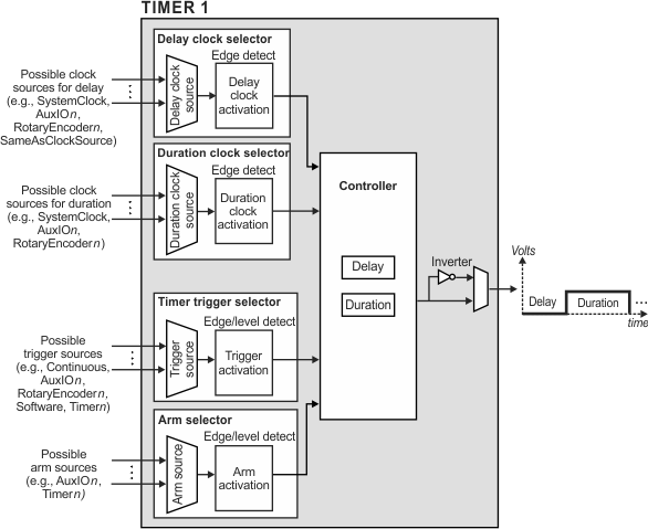
The diagram below shows a functional diagram of the internal organization of a timer in the Matrox Advanced I/O Engine.
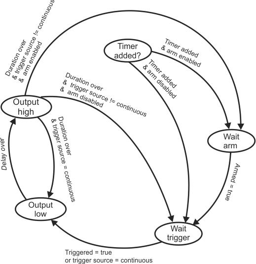
The diagram below illustrates the logic of the timer's controller.
Changing a timer's settings
at runtime
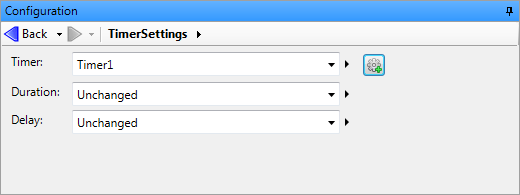
The TimerSettings step allows you to set the delay and/or duration of a timer during runtime. In the TimerSettings step's Configuration pane, you can select which timer to configure. Then, you can set the duration and/or delay to Unchanged, or to a user-defined value, an expression, or a link to a result.
Instead of using a TimerSettings step, you can also set a timer's duration and/or delay during runtime using platform configuration binding. See the Binding subsection of the Configuring input elements section in Chapter 50: Customizing the operator view for more information.
Rotary decoders
I/O command
lists
An I/O command list is used, by default, to schedule output commands issued by the IOWriter step (see the Procedure for using the IOWriter step subsection of the Procedure for using the I/O steps section earlier in this chapter). It can also queue and schedule output signals automatically generated from an input signal.
The commands in the list are executed at a specified moment. To schedule commands, the I/O command list uses an internal counter to count clock ticks or transitions that occur on a signal specified as the counter source. The counter source is set, by default, to the system clock, unless you add and connect input signals from a rotary encoder to your project. In this case, the counter source will change, by default, to the corresponding rotary decoder's output signal. For example, if you connect to a 2-bit quadrature rotary encoder, the decoded output will become the I/O command list's counter source.
You configure an I/O command list using the IO Command List Configuration options, accessible by clicking on the Advanced button in the IOs page of the Platform Configuration dialog, and then selecting I/O Command Lists from the presented list.
The following are the properties that you can configure for each I/O command list:
|
Property |
Description |
|
Enabled |
Sets whether the I/O command list is enabled. |
|
Source |
Sets the signal to use as the counter source. |
|
Activation |
Sets which edge of the source signal to use to increment the I/O command list's internal counter. This cannot be changed when using the system clock as the source. |
Command
list latches and reading their value with a TimeStamp or
PositionStamp step
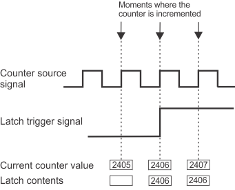
Each I/O command list has latches that are used to store the value of the I/O command list's internal counter in hardware, upon a signal transition of a specified input signal. Using a latch, you can obtain the counter value at a particular moment (for example, the moment when an object on a conveyor belt triggers a sensor along the path). The counter value is stored in the latch until another signal transition occurs, which will overwrite the contents of the latch.
You can change the properties of any available latch from the IO Command List Configuration options.
The following are the properties that you can configure for each latch:
|
Property |
Description |
|
Enabled |
Sets whether the latch is enabled. |
|
Trigger source |
Sets the signal to use as the trigger source for the latch. |
|
Activation |
Sets which edge of the trigger source signal to use to trigger the latch. |
You can retrieve the value of most latches using a TimeStamp step or PositionStamp step and setting the step's Source property to the name of the latch whose value to retrieve.
Matrox Design Assistant can reserve a specified latch to record the counter value at the moment when a grab is triggered; you can then set the delay of an IOWriter step relative to the value of this latch. To specify the latch with which to record the counter value upon a grab trigger, set the Grab reference source property in the physical camera page of the Cameras page in the Platform Configuration dialog; Matrox Design Assistant will automatically set up this latch. To retrieve the value of this particular latch, use Camera.GrabTime (if using the system clock as the counter source) or Camera.GrabPosition (if using a rotary decoder as the counter source) value. Note that in the case of Matrox 4Sight GPm, to ensure that you record the trigger actually used to start the grab of an image (and not a trigger ignored by the camera because a frame had already started being grabbed), you should connect the grab trigger signal to the unit and have the unit forward the trigger to the camera using an output signal; you must also enable the Use platform I/O(s) to synchronize capture and reference stamps option on the Cameras page of the Platform Configuration dialog.
Note that using a latch to record the moment when a grab is triggered is only for high-precision applications; if your application does not require very high precision, you can just trigger the camera and use the time when the image is received from the camera.
Scheduling I/O
commands
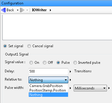
When using an IOWriter step to schedule an I/O command, you must specify when the command should occur. To do so, you specify a delay from a specific reference moment.
The delay can be relative to the moment at which the IOWriter step is run or the moment when a specified hardware event occurs. In the latter case, set the hardware event as the trigger source for one of the I/O command list's latches; the I/O command list's counter value will then be stored in this latch upon the specified hardware event. You can then schedule a command relative to the value of a PositionStamp step or TimeStamp step that reads this latch (depending on the counter source). If you are recording the moment when the grab is triggered in a latch as described above, you can also schedule output commands relative to this moment; to do so, set the Relative to property to Camera.GrabTime (if using the system clock as the counter source) or Camera.GrabPosition (if using a rotary decoder as the counter source).
Scheduling I/O
commands using rotary encoders
Using
an input to automatically generate a delayed pulse on output
When using Matrox Design Assistant with a runtime platform equipped with the Matrox Advanced I/O Engine, you can set an output signal to be automatically generated upon receiving a certain input signal, optionally after a specified delay. A transition on the input pin serves as a trigger for the output signal, and an I/O command list's latch is used to store the reference moment for the delay of the output signal. A typical use is to generate an output signal that is delayed from the input signal by a number of rotary transitions.
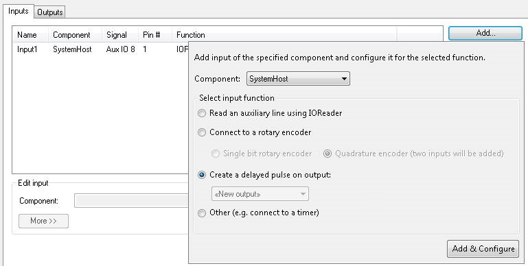
When adding an input signal in the Platform Configuration dialog, select the Create a delayed pulse on output option, as shown in the image below. In the dropdown list, you can select which output signal to trigger. If you select *New output*, a new output signal will automatically be added and configured. If you select an existing output signal, its current settings will be modified as necessary. Once added, you can configure an input or output signal's properties (for example, the delay and duration of the output signal) in the Inputs or Outputs tab, respectively, of the Platform Configuration dialog's IOs page. If the counter source of the I/O command list is a rotary decoder, specify the delay in decoder output signal transitions.
A delayed pulse on output can be used, for example, if there are multiple objects between the position at which objects are detected and the grab position. Each time an object is detected, a signal transition occurs on the appropriate input signal, which automatically adds an output command to an I/O command list, generating an output signal to grab an image when the object is at the appropriate position. The I/O command list queues the commands, allowing you to have multiple objects between the detection and grab positions.
Grab synchronization
with a reference stamp
If you route the acquisition trigger signal to an input of the Matrox Advanced I/O Engine and re-route it to a camera, Matrox Design Assistant can record the precise moment that the trigger signal is received and associate it with that camera. The recorded moment is a time or position, depending on the counter source of the I/O command list. You can use this reference stamp to synchronize multiple cameras or synchronize a camera with multiple outputs to different devices (for example, an ejector).
An example case is when you must ensure that grabbed images from multiple cameras are synchronized (originating from the same trigger). For example, if you have a multi-camera setup and your production line cannot be stopped during camera initialization, synchronizing a grab with a reference stamp enables each camera's grab to belong to the same trigger. For more information, see the Grabbing with the Matrox Advanced I/O Engine subsection of the Using multiple cameras section in Chapter 28: Acquisition.
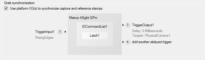
You can latch the precise time or position at which the trigger input signal is received by enabling the Use platform I/O(s) to synchronize capture and reference stamps checkbox on the Cameras page of the Platform Configuration dialog.
When you enable the Use platform I/O(s) to synchronize capture and reference stamps checkbox, as shown below, an auxiliary input signal (acquisition trigger input) and an auxiliary output signal (trigger output to the camera) are automatically added. When a trigger input signal is received, Matrox Design Assistant will store the value of the command list's internal counter in the next available latch of the first available command list. To enable or disable I/O command lists and latches, click on the IOCommandListN or LatchN button in the Cameras page, or click on the Advanced... button in the IOs page and choose IO command lists.... In the resulting dialog, you can also specify the counter source for a command list or a trigger source for one of its latches.
Once the input and output signals have been added, you can click
on the circled number ( ) to configure several of their properties. You
can set the input signal's name, activation edge (rising or
falling), and debounce time. For the output signal (trigger signal
for the camera), you can set the required delay. You can also set
the output signal's name, signal value (pulse or inverted pulse),
and pulse width. You can specify the delay and pulse width in msec
or decoder output signal transitions, depending on whether your I/O
command list's counter source is the clock or a rotary decoder. To
add and configure additional output signals to trigger other
cameras (if any output pins are available), see the
Using multiple cameras section in
Chapter 28: Acquisition. To configure outputs to other devices,
set them relative to the acquisition trigger input signal.
) to configure several of their properties. You
can set the input signal's name, activation edge (rising or
falling), and debounce time. For the output signal (trigger signal
for the camera), you can set the required delay. You can also set
the output signal's name, signal value (pulse or inverted pulse),
and pulse width. You can specify the delay and pulse width in msec
or decoder output signal transitions, depending on whether your I/O
command list's counter source is the clock or a rotary decoder. To
add and configure additional output signals to trigger other
cameras (if any output pins are available), see the
Using multiple cameras section in
Chapter 28: Acquisition. To configure outputs to other devices,
set them relative to the acquisition trigger input signal.
Note that, on the IOs page, the auxiliary input and
output signals used by this process are marked with an A for
automatic (![]() ). These signals cannot be removed from the
IOs page of the
Platform Configuration dialog. To remove these signals,
deselect the Use
platform I/O(s) to synchronize capture and reference stamps
option on the
Cameras page.
). These signals cannot be removed from the
IOs page of the
Platform Configuration dialog. To remove these signals,
deselect the Use
platform I/O(s) to synchronize capture and reference stamps
option on the
Cameras page.
To add and configure output signals that trigger other devices (for example, ejectors), use the IOs page of the Platform Configuration dialog. See the Procedure for using the I/O steps section earlier in this chapter.
Note that, to support multiple simultaneous runtime projects, each project must use its own set of input/output resources, such as rotary encoders, I/O command lists, and auxiliary input and output signals. For more information, see the Auxiliary I/O signals and related resources subsection of the Considerations when running multiple projects simultaneously section in Chapter 60: Running multiple projects on a runtime platform.
Outputting a
pulse train upon receiving an input signal
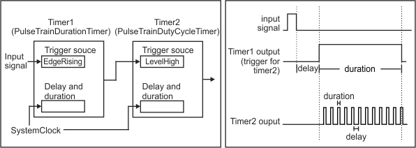
Upon receiving an input signal, you can also automatically generate an output signal with a pulse train (for example, to control a motion controller). To do so, you must use 2 timers: the first timer to control the duration of the pulse train and the second timer to control the duty-cycle of the pulse train.
To configure this in your project:
-
In the Platform Configuration dialog, add an input signal and an output signal to your project; for information, see the Configuring I/O pins subsection of the Procedure for using the I/O steps section earlier in this chapter. When adding the input signal, select the Other (e.g. connect to a timer) option.
-
Click on the Advanced button in the Outputs tab of the dialog, and then select Timers from the displayed list (Timer Configuration is presented).
-
Add a timer and rename it PulseTrainDurationTimer. Then, select and configure the timer as follows:
-
Set Trigger Source to the input signal.
-
Set Duration to the amount of time, in msec, to output the pulse train.
-
Set Delay to the required delay, in msec, before outputting the pulse train, once the timer is triggered.
-
-
Add a second timer and rename it PulseTrainDutyCycleTimer. Then, select and configure the timer as follows:
-
Set Trigger Source to the first timer, PulseTrainDurationTimer.
-
Set Trigger Activation to LevelHigh.
-
Set Duration to the amount of time, in msec, for the pulse train to be high (on) during its duty-cycle period.
-
Set Delay to the amount of time, in msec, for the pulse train to be low (off) during its duty-cycle period.
-
-
If the duration of the pulse train must be adjusted at runtime, bind a Textbox element directly to a platform configuration setting. Alternatively, add a TimerSettings step to your project, set the Timer input to PulseTrainDurationTimer, and link the Duration input to an expression or to the output of a step, or bind it to a Textbox element in the operator view. For more information, see the Configuring input elements section in Chapter 50: Customizing the operator view.