
I/O Examples
 Previous
- Next

The following sub-sections present 4 possible applications of communicating using I/O signals with the Matrox Advanced I/O Engine:
-
Automatically grabbing an image when the conveyor belt is at a given position.
-
Parts traveling along a conveyor belt that are fixed in spacing.
-
Different parts traveling along a conveyor belt that are ejected by different devices.
-
Parts traveling along a conveyor belt that are not fixed in spacing.
 Automatically
grabbing an image when the conveyor belt is at a given position
example
Automatically
grabbing an image when the conveyor belt is at a given position
example
In this example, parts are moving along a conveyor belt and are fixed in their position on the conveyor belt. The parts are always taking 100 rotary encoder steps forward before reaching a camera, which will take a picture of the conveyor belt beneath it. For simplicity, the conveyor belt can only move forward and the camera is a frame-scan camera. A sensor detects each time a part is on the conveyor belt, and a rotary encoder is used to tell the camera when the part is best placed to take the picture. The camera is triggered by a rising pulse.
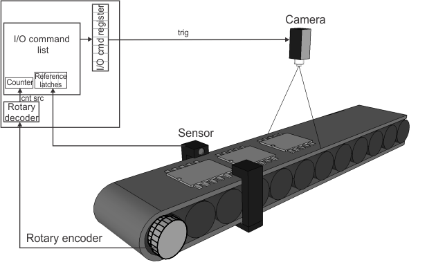
An I/O command list is used to cause the camera's trigger to activate. The rotary encoder output is used as the counter source of the I/O command list so that the scheduling of commands is based on a specified number of rotary encoder steps (distance that the part travels). Every time the sensor detects an object, it outputs a signal, causing a transition on a certain input pin. This triggers a latch to store the value of the command list's internal counter. The transition on this input pin is also set to automatically generate an output signal with a delay of 100 encoder transitions, causing the camera trigger's pulse to rise and a grab to occur. For information on how to set this up, see the Grab synchronization with a reference stamp subsection of the Matrox Advanced I/O Engine section earlier in this chapter. When the grab is complete, some processing is performed. This process repeats for each part passing the sensor. By setting the output to be automatically generated upon a transition on the input pin, you guarantee that every time the latch fires, a grab will occur.
Parts
traveling along a conveyor belt that are fixed in spacing
example
In this example, parts are moving along a conveyor belt but are fixed in their position on the conveyor belt. The parts are always taking 500 rotary encoder transitions forward before reaching an ejector, which will discard the part if processing fails. For simplicity, the conveyor belt can only move forward and the camera is a frame-scan camera. A sensor detects each time a part is under the camera's field of view; the sensor's signal is used to trigger the grab. The ejector requires a pulse of 10 msec (0.01 sec) to succesfully redirect a part.
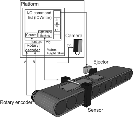
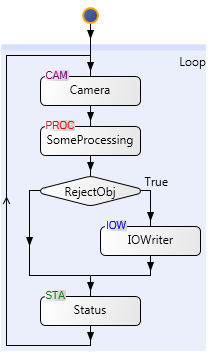
3 input signals are added using the Platform Configuration dialog. 2 will be used for the quadrature input from the rotary encoder and one will be used as the latch trigger signal. The rotary encoder is used as the counter source for the I/O command list, which is used as the common reference signal relating grab time to ejector time. The latch trigger signal is used to retrieve the value of the counter at the moment a part enters the camera's field of view (represented by Camera.GrabPosition). One output signal is added as the output of I/O command list 1. After the Camera step fetches an image, some processing is performed. After the processing has completed, a condition is added to determine if the part should be ejected or continue on. If the part is to be ejected, a command is added to the I/O command list using the IOWriter step, with a delay of 500 transitions, relative to Camera.GrabPosition, and a pulse width of 10 msec.
Different
parts traveling along a conveyor belt that are ejected by different
devices example
In this example, 3 different parts are moving along a conveyor belt and each different part needs to be redirected to a different path. This could be used, for example, if the objects are graded according to the results of the inspection, and must be redirected along different paths depending on their grade. 3 ejectors redirect the different parts to the correct path. Each ejector is a known distance away from a sensor that triggers the grab. Parts of type "A" are redirected by ejector A, which is 800 rotary encoder steps away from the sensor; parts of type "B" are redirected by ejector B, which is 1000 rotary encoder steps away from the sensor. Parts of type "C" are redirected by ejector C, which is 1200 rotary encoder steps away from the sensor. All 3 ejectors require a pulse of 10 msec (0.01 sec) to succesfully redirect a part.
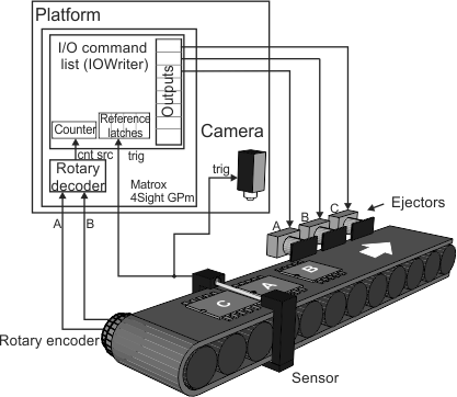
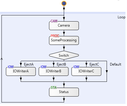
3 input signals and 3 output signals are added using the Platform Configuration dialog. 2 inputs will be used for the quadrature input from the rotary encoder and one will be used as the latch trigger signal. The rotary encoder is used as the counter source of the I/O command list, which is used as the common reference signal relating grab time to ejector time. The latch trigger signal is used to retrieve the value of the counter at the moment a part enters the camera's field of view (represented by Camera.GrabPosition). 3 output signals are added: Output A, Output B, and Output C; they are each connnected to their respective ejectors. After the Camera step fetches an image, some processing is performed. After the processing has completed, a Switch step is added based on the results of the processing. If processing determined the part is of type A, a command is added to the I/O command list using IOWriter step for Output 1, with a delay of 800 transitions, relative to Camera.GrabPosition, and a pulse width of 10 msec. If the part is of type B, a command is added to the I/O command list using IOWriter step for Output 2, with a delay of 1000 transitions, relative to Camera.GrabPosition, and a pulse width of 10 msec. If the part is of type C, a command is added to the I/O command list using IOWriter step for Output 3, with a delay of 1200 transitions, relative to Camera.GrabPosition, and a pulse width of 10 msec.
Parts
traveling along a conveyor belt that are not fixed in spacing
example
In this example, parts are moving along a conveyor belt, where the spacing between each object change as they move along the conveyor but not changing the sequence with which they reach the ejector. The parts take a variable number of rotary encoder transitions before reaching the ejector, which will discard the part if processing fails. 2 sensors are placed along the conveyor belt. Sensor A is placed where the part is completely in the camera's field of view; while, sensor B is placed near the ejector such that when the part is no longer detected, it is completely in front of the ejector. The ejector requires a pulse of 10 msec (0.01 sec) to succesfully redirect a part.
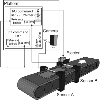
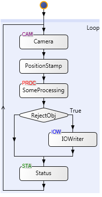
2 input signals are added using the Platform configuration dialog. The signal coming from sensor A will be used as the counter source for IOCommandList1 and the latch trigger signal for a latch on IOCommandList1 and a latch on IOCommandList2. The signal coming from sensor B will be used as the counter source for IOCommandList2. One output signal is added as the output of IOCommandList2 and it is connected to the ejector. In the PhysicalCamera1 page of the Platform Configuration dialog, select IOCommandList1Latch1 as the Grab reference source; this will allow you to retrieve the number of parts that have passed by sensor A with the Camera.GrabPosition value. After the Camera step grabs an image, the PositionStamp step runs to provide access to the value stored in the latch of IOCommandList2; this allows you to retrieve the number of parts that have passed by sensor B when a new part enters between sensors A and B with the PositionStamp.Position value. After the processing has completed, a condition is added to determine if the part should be ejected or continue on. If the part is to be ejected, a command is added to the I/O command list using the IOWriter step to change the output signal connected to the ejector such that the ejector ejects the correct part. This is done by waiting until the number of parts between sensors A and B pass by sensor B; in the Configuration pane of the IOWriter step, set the delay equal to the number of parts between sensor A and sensor B (Camera.GrabPosition - PositionStamp.Position), relative to PositionStamp.Position, and a pulse width of 10 msec.