
Procedure for using the I/O steps
The following steps provide a basic procedure for communicating with Matrox Design Assistant using I/O pins :
-
Add and configure each I/O pin that will be needed for your project according to its purpose.
-
Add an IOReader step each time you need to read the value of I/O pins.
-
Add an IOWriter step each time you need to set the value of any defined I/O pins.
-
Optionally, to change delay and duration settings during runtime, bind input elements in the operator view directly to platform configuration settings or to an IOSettings step, or link a Button element to an operator view action.
Note that if your runtime platform is equipped with the Matrox Advanced I/O Engine, you can receive inputs and schedule outputs more efficiently, without using any IOReader steps or IOWriter steps.
 Configuring I/O
pins
Configuring I/O
pins
The IOs page of the Platform Configuration dialog lets you associate the name used inside the flowchart's IOReader step or IOWriter step with a physical input or output pin. The I/O page also allows you to configure the various properties of each input and output pin. Note that some properties are only available on certain runtime platforms.
The following is the basic procedure to configure I/O signals:
-
Navigate to the IOs page of the Platform Configuration dialog using the Project Configure I/O... menu item or the Configure platform (
 ) toolbar button in the
Platform toolbar .
) toolbar button in the
Platform toolbar . -
If you want to know how many input, output, and bidirectional pins are available on your runtime platform, use the List the Available I/Os button in the IOs page of the Platform Configuration dialog. You are not able to add more pins than are supported on your runtime platform. For information about what constitutes support, see the Support for I/O subsection of the IO steps overview section earlier in this chapter.
-
Add input and output signals (pins) to the Inputs tab or Outputs tab, respectively.
When you add an input pin on a runtime platform equipped with the Matrox Advanced I/O Engine, you will be presented with the following 3 options:
-
Read an auxiliary line using IOReader. Select this option if your project will only use an IOReader step to read the state of the pin.
-
Connect to a rotary encoder. Select this option if you want the pin to serve as an input for a rotary decoder on the runtime platform. If you select the Quadrature encoder option, 2 pins will be added for the 2-bit quadrature input. For information on rotary encoders and decoders, see the Rotary decoders subsection of the Matrox Advanced I/O Engine section later in this chapter.
-
Create a delayed pulse on output. Select this option to have the input signal, arriving on the pin, trigger the generation of a delayed pulse on an output pin. If you select this option, an output pin will automatically be added. For more information, see the Using an input to automatically generate a delayed pulse on output subsection of the Matrox Advanced I/O Engine section later in this chapter.
-
Other (e.g. connect to a timer). Select this option to have the input signal, arriving on the pin, trigger something other than an item mentioned above (for example, a timer).
Choosing any one of these options will automatically configure several elements of the I/O interface, using the next available resource when adding input signals.
Regardless of the option chosen, you can always use the input signal, arriving on a pin, to trigger acquisition.
By default, signals are added to successive pins. If you want to change the pin to one that is not yet allocated, select the required pin's auxiliary number from the Signal dropdown list. If the required pin is already allocated, use the Up and Down arrows to move the selected item in the list, until it has the required pin.
-
-
For each I/O pin, adjust the properties as necessary. It is recommended to give each signal a meaningful name.
The following are properties of both input and output pins:
|
Property |
Description |
|
Name |
Different runtime platforms (for example, a supported Matrox smart camera) differ in the number and allocation of I/O pins. Therefore, when developing projects that might be used on different runtime platforms, it is better to give each pin a meaningful Name, rather than just using their defaults. |
|
Component |
The Component property allows you to specify the hardware component on which the pin is located. If only a single piece of hardware in your runtime platform provides I/O signals (for example, when connected to a Matrox smart camera or a GigE/USB3 Vision camera with I/O connected to a 3rd party PC), there is no need to change the default setting. When you have one or more GigE/USB3 Vision cameras connected to a Matrox PC, you have access to the sum of the supported I/Os on all connected hardware. For example, if a GigE Vision camera with 4 I/O pins is connected to a Matrox 4Sight GPm unit, there is a total of 12 I/O pins, because the camera has 4 I/O pins and Matrox 4Sight GPm has an additional 8 iI/O pins. To control a pin on the unit, set Component to default; to control a pin (line) on the camera, set Component to the name of the GigE system. |
|
Signal |
The Signal property corresponds to a pin's identifier in the underlying MIL library. Each signal is mapped to a specific physical pin, so specifying the signal is selecting the pin that is used for that signal. On a supported Matrox smart camera, Matrox 4Sight, or PC with Matrox Indio, the pin(s) corresponding to the signal is indicated in the IOs page. For GigE/USB3 Vision cameras, you can find this information in your camera's technical documentation, or by contacting the manufacturer. |
|
Pin Number |
On supported Matrox runtime platforms, the Pin Number property corresponds to the physical connector. To change the pin number, select the item and use up/down arrows to move the input or output to another pin. |
The following are properties available only for each input pin:
|
Property |
Description |
|
Active Edge |
This option specifies the active transition of the input signal. The active edge is used in transition counting or as the default activation source. |
|
Count Transitions |
This property tells you how many times the signal has transitioned since the last time the signal was read by a specific IOReader step. This allows you to know if a signal arrived while the flowchart was still busy with other steps. Note that there is a transition count for each IOReader step in your flowchart. |
|
Debounce Time |
Set the Debounce Time property to reduce the effect of noisy input signals , and mechanical switch bounce. The signal must remain stable for the specified time before it is considered valid. |
|
Glitch Filter |
Sets whether to enable a glitch filter on input signals. A glitch is an unexpected signal transition of a short duration. Enabling a glitch filter will eliminate glitches of less than 500 nsec on all input signals. |
The following are properties available only for each output pin:
|
Property |
Description |
|
Source |
The Source property selects an output signal for the pins that can have different signals associated with them. The Source dropdown list will provide all the available options for the currently connected runtime platform. Specifying IOWriter means that an IOWriter step in the flowchart can activate the signal. Specifying any other option means that the specified hardware (for example, a timer) will generate the signal. Note that the IOWriter step can only see and use the pins whose source is set to IOWriter. Each I/O pin can have different sources. IOWriter mode is flowchart controlled. The other values allow sending a hardware generated signal (for example, an exposure or strobe signal). Also, an input trigger signal can be echoed onto an output. For more information about the exposure or strobe signal, see Platform settings for your camera. For more information on using the output pins for strobe, exposure, or trigger bypass, consult the Installation and Technical Reference manual. |
|
IO Command List |
This option selects the I/O command list in which commands for the specific output will be written. This is only available on runtime platforms equipped with the Matrox Advanced I/O Engine section later in this chapter. For more information on I/O command lists, see the I/O command lists subsection of the Matrox Advanced I/O Engine section later in this chapter. |
|
Output Mode |
The Output Mode property specifies a low level configuration setting. Use the default. |
The options available in the Component property depend on the hardware that makes up your runtime platform. The options are cumulative, which means that if you have both a Matrox PC and a GigE/USB3 Vision camera with supported I/O, you will have both SystemHost and PhysicalCameraN as options.
|
Runtime platform hardware |
I/O components from which to choose |
|
Supported Matrox smart camera |
|
|
Matrox 4Sight and GigE/USB3 Vision camera with supported I/O |
|
|
Third-party PC and GigE/USB3 Vision camera with supported I/O |
|
Procedure for using the
IOReader step
The IOReader step requires no setup in the user interface. Other steps can simply link to and use the information received through this step. For example, the Condition step can link to the IOReader step to control the flow of your project based on the state of the signal arriving on a specified input pin.
When the IOReader step is run, the signal is read and its current value is returned. Since the read is polled and not event-driven, it is necessary to have a way to know if the signal was active while it was not being checked. You can track the number of times that a signal arrives at a specified pin using the global TransitionCount property, accessible from an IOReader step at IOReader.Pins("InputPinName").TransitionCount. This count increments each time a signal is received on a specified pin, regardless of whether an IOReader step actually reads it. For each pin, you can determine how many signals were received but not read (missed) by an IOReader step using the IOReader.Pins("InputPinName").TransitionCountDelta property. An IOReader step stores the global TransitionCount for each pin the last time that the step was executed. The TransitionCountDelta property is the difference between the current TransitionCount and the stored TransitionCount for that step. Note that this can be especially important when using 2 or more IOReader steps that read from the same pin.
Converting pin values to
numbers
Procedure for using the
IOWriter step
Changing the I/O settings at
runtime
Platform configuration binding and the IOSettings step allow changes to be made to certain input and output signal settings at runtime. This allows you to make changes to inputs that control the timing (for example, delay and duration) from the operator view without having to re-deploy your project.
To bind operator view input elements directly to platform configuration settings, see the Binding subsection of the Configuring input elements section in Chapter 50: Customizing the operator view. To incorporate the IOSettings step in your project, add it to a subflowchart and adjust the required settings in the IOSettings step's Configuration pane.
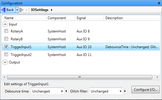
For input signals, you can directly bind operator view input elements, or use the IOSettings step, to set the Debounce time and the Glitch filter inputs. Similarly, for output signals, the Delay and the Pulse width inputs can be set.