Using I/O steps with GigE/USB3 Vision cameras
Input/output lines (signals) of compliant GigE/USB3 Vision cameras can be configured from the IOs page of the Platform Configuration dialog.
 Configuring
your I/O signals
Configuring
your I/O signals
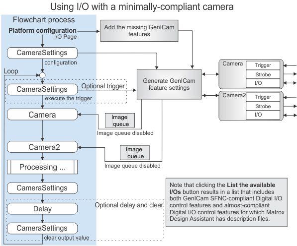
Using I/O with a
minimally-compliant camera
If using a GenICam SFNC-compliant camera, Matrox Design Assistant should display the digital I/O features of the camera (and, by association, all its I/O signals). However, for some cameras, clicking on the List the Available I/Os button in the IOs page of the Platform Configuration dialog fails to list the expected inputs and outputs. If this is the case, contact Matrox customer support. An I/O descriptor file might be required to fix recognition errors.
If you are using a GigE/USB3 Vision camera for which Matrox Design Assistant does not recognize its full I/O capability, instead of an IOWriter step, use the Edit GenICam features button in a CameraSettings step to configure the features and their values.
Depending on the feature and the camera manufacturer, some settings cannot be applied in the middle of an acquisition. Such settings might take a long time to be set on the camera. For best results, separate the configuration that only needs to be done once (such as determining I/O sources) from that which must be done in the middle of the flowchart. Always limit the number of GenICam features to be set within your flowchart's main inspection loop.
Note that, to adjust a GenICam camera's settings at runtime, ensure your project calls a subflowchart with a CameraSettings step.
In the following example, Line4 on a GigE Vision camera is a camera output signal (pin) that we want to use to return the value of the ExposureActive feature, which is internal to the camera.
-
At the top of the flowchart, add a CameraSettings step.
-
In the CameraSettings step's Configuration pane, click on the Edit GenICam features... button.
-
In the GenICam Features page, find the LineSelector feature and set it to Line4. Then, click on the Add button.
Note that, to quickly get to the features that you want to control, type Line into the Filtered by name text box. The feature list will automatically scroll to the correct location and display information about features starting with "line", such as the LineSelector feature.
-
Select the LineSource feature from the available list of options, and change its value to ExposureActive. Then, click on the Add button.
If you change a feature's value with the CameraSettings step, the CameraSettings step stores this feature's value with your project. When your project is run, the feature's value will be changed on your camera.