
IO steps overview
 Previous
- Next

Matrox Design Assistant allows you to communicate with external devices via the discrete I/O pins (auxiliary I/O pins) of your runtime platform's input and output connectors , if the platform is a Matrox smart camera, a Matrox 4Sight GP/GPm, or a PC equipped with a Matrox Indio board. When using a PC runtime platform, Matrox Design Assistant can also communicate with external devices via the I/O pins of the input and output connectors of any connected GigE/USB3 Vision camera that supports I/O. Matrox Design Assistant can also use the additional I/O capabilities of runtime platforms equipped with the Matrox Advanced I/O Engine.
You must specify which I/O pins your project will use and configure how a signal should be transmitted/received on these pins, using the Platform Configuration dialog.
In addition, you can use platform configuration binding or an IOSettings step to change certain configuration settings of the input and output signals during runtime.
The IOReader step allows you to read the value of an auxiliary input signal. The IOWriter step allows you to set the value of an auxiliary output signal.
Depending on the hardware available, auxiliary input signals can be used with Matrox Design Assistant to perform the following typical tasks:
-
Use an input signal to trigger a camera to grab an image.
-
Read the value of an input pin and have the flowchart perform an operation according to that value (for example, check if a safety door is closed).
-
Upon receiving an input signal, generate an output signal (often a pulse) after a certain delay (for example, to trigger some distance further down a conveyer from the part detector).
-
Take one or 2 rotary encoder inputs and use them as the clock for position stamps and the delay of output signals.
-
Relay a trigger signal after having accurately latched the time/position at which it arrived.
-
Use an input signal, along with 2 timers, as control for outputting a pulse train.
Depending on the hardware available, auxiliary output signals can be used with Matrox Design Assistant to communicate to an external device or controller via:
-
An IOWriter step.
-
An automatic output tied to an input.
-
A timer output.
 Support for I/O
Projects with
discrete I/O
When you create a project that uses a certain number of I/O pins, these settings are saved to the project. Consequently, a project that uses I/O can only be deployed on a runtime platform that supports I/O capabilities (see the Support for I/O subsection of this section). However, this can be problematic when a project is developed for a platform with a certain number of I/O pins, and is opened while connected to a platform that has fewer I/O resources.
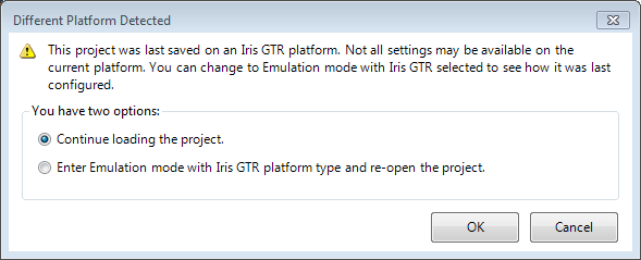
If you open a project that was originally developed using a different platform than the one to which you are currently connected, a warning dialog will appear, as shown below. You can either emulate the platform on which the project was originally developed, or continue opening the project. However, if you choose the latter option on a platform that has fewer I/O pins than are used in the project, you will see errors in the IOs page of the Platform Configuration dialog and in the Errors pane.
Alternatively, reconnect to a runtime platform with the correct number of I/O pins, using the Platform menu.