Real-world units and fixtures
In Matrox Design Assistant, you are able to calibrate your camera and fixture objects, allowing you to, for example, consistently place search regions and retrieve results.
 Calibration
Fixturing
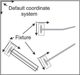
Matrox Design Assistant supports fixturing. A fixture defines a relative coordinate system and consists of a point of origin and an angle. Once a fixture has been created, any step can use this fixture.
Fixturing is often used when the objects that need analyzing can appear in different places in the image. For example, a ModelFinder step determines the location of the object in the image, and then creates a fixture based on the object's variable location and orientation. This allows the object to be in a different position for each image taken, while not affecting the search areas and regions of interest of the subsequent steps.
While search regions are usually fixtured, step position and angle results are, by default, produced with respect to the absolute coordinate system, which has its origin at the top leftmost point of the image or at the calibrated origin. By fixturing a search region, the region will be oriented with respect to the fixture's coordinate system instead of the absolute coordinate system. Although not normally done, you can also specify a fixture for the output coordinate system; in this case, any results returned by a step are relative to the fixture's coordinate system. Note that a step's search region's fixture and its output coordinate system's fixture can be different.
Matrox Design Assistant has several steps that can create fixtures. A project can have multiple distinct fixtures that are usable by other steps. Any search region that can use a fixture can select one in the Fixture dropdown list located in the construction pop-up window. The construction pop-up window appears when creating or redefining a shape (in this case, a search region).
For more detailed information, see Chapter 32: Fixturing.
An
example of calibration and fixturing
To measure the width, in mm, of an object that will appear in different places in sequential images, the following flowchart could be used:
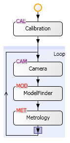
The Calibration step appears first and outside of the main loop. Configure this step so that, for example, every 5 pixels is 1 mm; see the Procedure for using the Calibration step section in Chapter 30: Calibration for how to create a calibration file. Associate the image created in the Camera step with the calibration file created in the Calibration step; see the Procedure for using the Camera step section in Chapter 28: Acquisition for the correct procedure. Configure the ModelFinder step to find and fixture the object, regardless of the object's location in the image. Enter the fixture, created in the ModelFinder step, in the Output coordinates property of the Metrology step. This can be done by selecting the correct fixture from the list in the Output coordinates dropdown list, found in the Configuration pane of the Metrology step. Set the Metrology step to output the width of the object. See Chapter 13: ModelFinder step and Chapter 18: Metrology step for the appropriate procedures.