Procedure for using the Calibration step
The following provides a basic methodology for using the Calibration step.
-
Select the Method to use for calibration.
-
Specify a CalibrationName. This name will be used to identify the calibration in Matrox Design Assistant, and the file name it is saved with.
-
Optionally, set SaveCalibration to True to store the calibration file to the supported Matrox smart camera. This will allow you to reuse the calibration in other projects. Note that you cannot store the calibration file to the camera if you are running Matrox Design Assistant in Emulation mode.
Note that if you specify a CalibrationName which already exists and save the calibration to a calibration file, the old file will be overwritten by the new one.
 Scale method
ListOfPoints
method
ListOfPointsFromArray
method
Grid method
The Grid method requires an image with a chessboard grid or a rectangular array of dots that are uniformly spaced in world coordinates, but can be distorted in the image. You have to specify the Grid Type you are using: either a CircleGrid or a ChessboardGrid. See the Grid requirements subsection of this section.
Set the Mode to Perspective if the camera is not perpendicular to the object and there is no curved distortion. LinearInterpolation mode is used for other types of distortion, such as radial, fisheye, or pincushion distortion; your grid should have enough points so that the curved distortion between 2 points is insignificant.
Indicate the Number of rows and Number of columns of dots or chessboard intersections in the calibration image. Note that for the chessboard grid, the number of intersections is counted, rather than the number of squares. Thus these properties indicate the total number of squares -1. Note also that columns are always perpendicular to the X-axis.
The Row spacing and Column spacing properties are the world coordinate distances between adjacent dots, or the size of the chessboard squares.
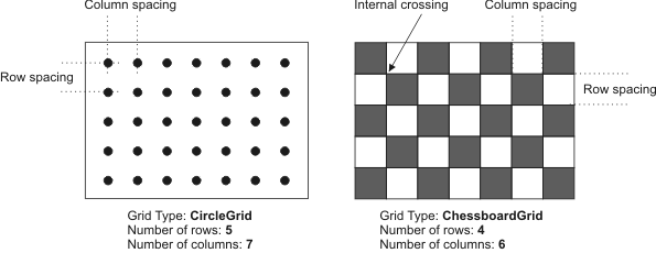
Note that the RowNumber and ColumnsNumber properties in the chessboard grid refer to the number of internal crossings, and are therefore one less that you would expect (see the above illustration). The minimum acceptable size for a chessboard grid is a grid with 4 internal crossings.
The Foreground property specifies the color of the dots (either Black or White), and does not apply to the chessboard grid.
The Offset X and Offset Y properties specify the world coordinates of the center of the dot or chessboard square that are closest to the top-left corner of the image or the corner specified by a corner hint.
The Grid corner hint coordinates indicate the approximate pixel-coordinate location of the closest corner, giving the software a hint where it can find the grid in the calibration image.
The Y-axis orientation is set to Down by default, and can be changed if the Y-axis of the image is oriented upward instead. Note that to set the origin in a different quadrant, the pixel coordinate system essentially rotates around the grid.
The following image shows the different pixel coordinate system orientations you can encounter. Note that the bold X in each grid is a Grid corner hint:
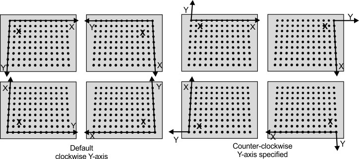
If the grid appears in the image such that the grid's reference calibration point is not in the top-left corner of the image, you must specify where it is in the image. The solution is to specify a Grid corner hint, such that a hint point that is close to the grid's reference calibration point is set in the rotated image. To do so, set the Grid corner hint X & Y pixel coordinates. They do not have to be precise since the closest actual corner to the specified coordinates will be used as the grid's reference point.
Grid
requirements
To create and accurate mapping, your grid must have a minimum number of points and meet a set of guidelines depening on the type of grid.
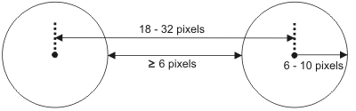
For a circle grid: the grid must have at least 2 rows and 2 columns of calibration points. The radius of the dots should range between 6 and 10 pixels, the center-to-center distance between the dots should range from 18 to 32 pixels, and the minimum distance between the edges of the dots should be 6 pixels.
For a chessboard grid: the grid should have at least 3 rows and 3 columns of calibration points (which requires at least 4 rows and 4 columns of squares). The entire grid should appear in the field of view; partial grids are not supported. The grid squares should be at least 12 x 12 pixels in size, and the grid should have little to no saturation.
For either type of grid: the grid should be large enough to cover the working area of the image, and should have high contrast and be free of specks, dirt, noise, or other imperfections.
Choosing a
calibration mode
When you use any method of calibration that uses a point mapping (that is ListOfPoints, ListOfPointsFromArray, or Grid) you get the choice between 2 modes of calibration: Perspective, and LinearInterpolation.
Perspective mode corrects for perspective distortion. It is simpler than LinearInterpolation, and requires fewer points as input to work properly. Below is an example of perspective correction:
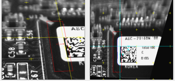
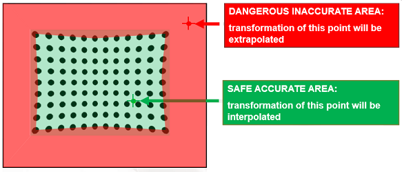
Linear interpolation requires more points (it is recommended that you use 5 points or more) and corrects for other types of distortion, such as radial, fisheye, or pincushion distortion. Linear interpolation is only accurate inside the area of given points (that is, inside the grid you provide). Outside of the grid, the calibration can only extrapolate, which is not accurate. For this reason, if you use linear interpolation, make sure your grid or set of points covers the working area of your image.
The Valid region annotation provided by the Calibration step when using LinearInterpolation mode shows the area in the image where calibration is accurate.