
Procedure for communicating with controllers
The following steps provide a basic methodology for communicating with a PLC using the PROFINET or EtherNet/IP protocol:
-
Using an appropriate configuration software package, configure your PLC to recognize your runtime platform as a slave device (scanner). Refer to the sections on setting up for PROFINET and EtherNet/IP, later in this chapter, for more information.
-
Use the MILConfig utility to enable the protocol service for your runtime platform.
-
In Matrox Design Assistant, enable the protocol for your project.
-
Read data from the PLC using Quick Comm, the ProfinetReader step, or the EthernetIPReader step.
-
Perform some inspection and analysis operations.
-
Write data back to the PLC using Quick Comm, the ProfinetWriter step, or the EthernetIPWriter step.
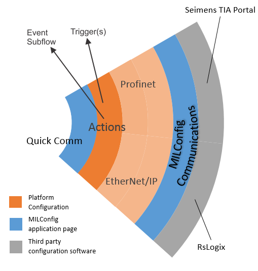
The diagram below displays an overview of the PROFINET and EtherNet/IP industrial protocols in Matrox Design Assistant.
 Enabling the
PROFINET and EtherNet/IP protocol service
Enabling the
PROFINET and EtherNet/IP protocol service
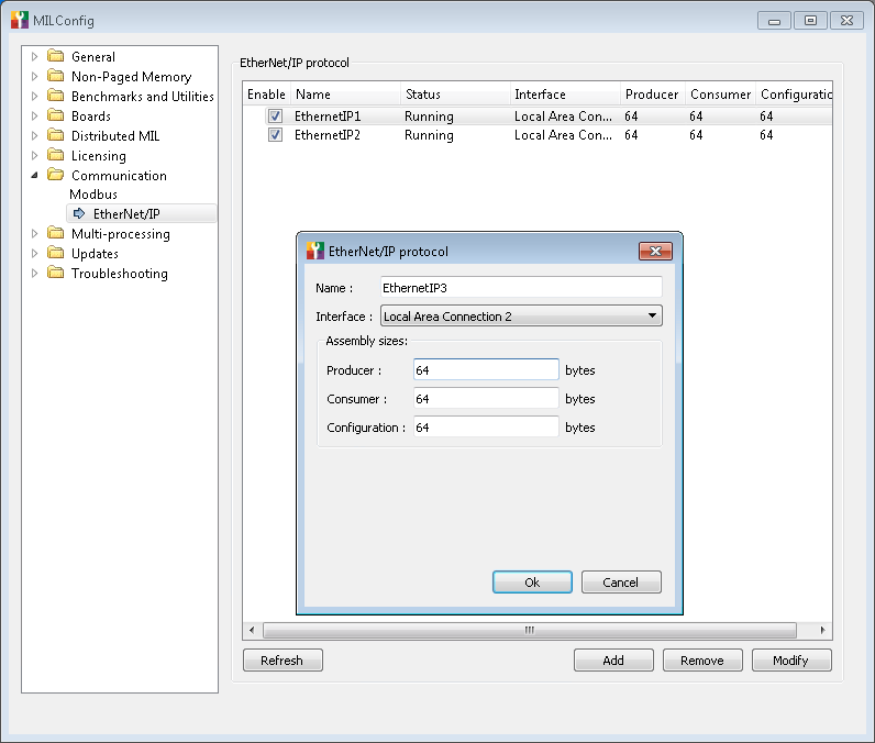
To communicate with a PLC using the PROFINET or EtherNet/IP protocol on your runtime platform, you must enable the protocol service by opening the MILConfig utility on the runtime platform, expanding the Communication item, selecting the EtherNet/IP or PROFINET page, and adding, removing, or modifying protocol instances (instance names are case sensitive). If your runtime platform has multiple network adapters (NICs), you can select which one to use from the Interface dropdown list.
If you are using a remote PC or a smart camera as your runtime
platform, opening the MILConfig utility on it might require remote
desktop or VNC access. On a Matrox Iris GTR smart camera, you can
create, enable, and modify protocol instances directly from its
COMMUNICATION portal pages, accessible using the
Administration
button ( ).
).
Once the protocol instance has been created on your runtime platform using the MILConfig utility, you need to enable the protocol for your project by selecting the Configure EtherNet/IP or Configure Profinet menu item from the Project menu. This will open the Platform Configuration dialog to the relevant page, and you can enable the protocol by clicking on the EtherNet/IP or Profinet slider. Make sure to verify the name of the instance needed for your project. The slider will turn green, indicating that the protocol is now enabled for your project. By default, this also enables the Quick Comm feature. To disable it, click on the Quick Comm slider in the same dialog.
Alternatively, you can enable the protocol instance in the Communications dropdown panel, accessible from the Matrox Design Assistant platform toolbar. Note that, when using this method, you cannot select a different instance of the protocol.
You cannot enable both the PROFINET and EtherNet/IP protocols in the same project. Matrox Design Assistant will automatically disable one when you enable the other.
For information about running multiple projects simultaneously, and the restrictions for projects that use industrial protocols, see the Communication protocols subsection of the Considerations when running multiple projects simultaneously section in Chapter 60: Running multiple projects on a runtime platform.
Quick Comm with PROFINET
and EtherNet/IP
Matrox Design Assistant's Quick Comm feature is implemented as a combination of predefined data fields in data tables and action points in the flowchart. These data fields are waited for, read, set, and reset in the background. The handshake, including overall pass and fail status, is done without the need to add any steps in the flowchart. Event-triggered actions allow Quick Comm to perform the handshake between the runtime platform and the PLC. For information on actions and events, see the Events and actions section in Chapter 2: Building a project.
You can enable or disable Quick Comm at any time during the development of a project either in the Platform Configuration dialog or in the Communications dropdown panel.
Status and
control handshake
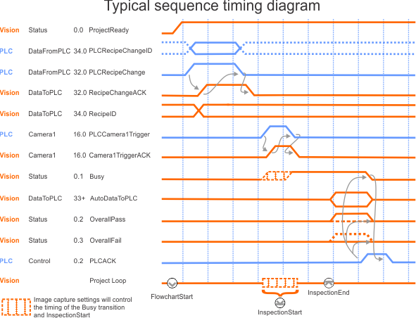
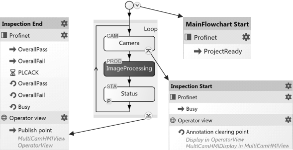
The standard data fields set by the PLC indicate that the camera should be triggered, and that the results of the analysis have been acknowledged. Data fields sent to the PLC indicate if the project is ready or busy, and indicate an OverallPass and OverallFail status based on the results in the Status step. There are also Quick Comm data fields that are dedicated to triggering image acquisition for up to 8 cameras. The images below illustrate the standard handshake.
If you are not using Quick Comm, see the Using a PLC trigger without Quick Comm subsection of the Triggering section in Chapter 28: Acquisition for information.
At runtime, a wait banner appears in the operator view if a running project is waiting for a handshake from the PLC. At design-time, the Wait notification bar blinks at the bottom of the flowchart and offers the option to skip the wait or see which bit is being waited for.
Optionally, applications can make use of additional data fields (such as PLCReset, and PLC event fields). You must set the address of each data table to match the expected address in your PLC's data map. More sophisticated multiple-camera applications can also use per camera trigger and per camera pass/fail fields for up to 8 cameras. By default, the PROFINET and EthernetIP pages in the Platform Configuration dialog only display data fields associated with events, but all fields in the data tables can be seen by toggling the Only show fields with events option.
The table below lists the predefined data fields, when Quick Comm is enabled. Their exact addresses are protocol dependent.
|
Data fields |
||||||||
|
Data table |
Bit 0 |
Bit 1 |
Bit 2 |
Bit 3 |
Bit 4 |
Bit 5 |
Bit 6 |
Bit 7 |
|
Control |
(Reserved) |
PLCReset |
PLCACK |
(Reserved) |
(Reserved) |
PLCSoftEvent1 |
PLCSoftEvent2 |
(Reserved) |
|
Status |
ProjectReady |
Busy |
OverallPass |
OverallFail |
(Reserved) |
SoftEvent1ACK |
SoftEvent2ACK |
Online |
|
Camera1 |
(Reserved) |
(Reserved) |
Camera1Pass |
Camera1Fail |
(Reserved) |
Camera1SoftEvent1ACK |
Camera1SoftEvent2ACK |
(Reserved) |
|
PLCCamera1Trigger |
(Reserved) |
(Reserved) |
(Reserved) |
(Reserved) |
PLCCamera1SoftEvent1 |
PLCCamera1SoftEvent2 |
(Reserved) |
|
|
. Up to 8 Camera data tables . |
||||||||
|
DataToPLC |
16, 32, 64, 128, 256, 512, 1024 bytes of user-defined fields (Bit, Byte, Word, DWord, Float, String) |
|||||||
|
DataFromPLC |
16, 32, 64, 128, 256, 512, 1024 bytes of user-defined fields (Bit, Byte, Word, DWord, Float, String) |
|||||||
|
Inputs: Written to the PLC |
||||||||
|
Outputs: Read from the PLC |
||||||||
Matrox Design Assistant allows you to define custom actions and events, for some data fields, in the Actions page of the Platform Configuration dialog. For more information, see the Configuring actions and events section later in this chapter.
Set Quick Comm
to trigger acquisition automatically
Sending and
receiving data
Using Quick Comm, projects can be configured so that data is automatically sent to the PLC when the Inspection End Action point is reached. You can configure application-specific data fields to be automatically updated with data to be sent to the PLC in the DataToPLC page of the Platform Configuration dialog. Application-specific data for input to the runtime platform from the PLC is configured in the DataFromPLC page of the Platform Configuration dialog, but does not have the option to update automatically.
If you load a project that was created prior to Matrox Design Assistant 5.0, it will not be automatically upgraded to use the Quick Comm feature, because its data mapping does not match that defined by Quick Comm. All the fields in the project are added to the DataToPLC and DataFromPLC tables. Consequently, reader and writer steps are also provided in Matrox Design Assistant X Version 1905 for legacy projects to communicate with a PLC.