Setting up for PROFINET
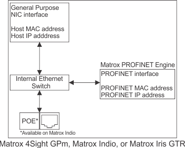
To use the PROFINET industrial communication protocol, your runtime platform requires a Matrox PROFINET Engine (available on Matrox Iris GTR, Matrox 4Sight GPm, or a computer with Matrox Indio). When you enable an instance of the PROFINET service associated with the engine (NIC), the Matrox PROFINET Engine activates its hardware-assisted PROFINET interface.
When activated, the PROFINET interface is able to act as a second Ethernet communication device with its own MAC and IP settings; these settings are distinct from those of the main Ethernet communication interface available to the operating system (the second Ethernet communication device is not accessible by the operating system). The LAN connection associated with the PROFINET interface is shared with other Ethernet traffic. The 2 Ethernet communication channels can be represented as follows:
Note that, every running project that uses the PROFINET industrial communication protocol requires its own Matrox PROFINET Engine (NIC). For example, to simultaneously run 3 projects that use the PROFINET protocol, your runtime platform must have 3 Matrox PROFINET Engines (NICs), such as 3 Matrox Indios. For more information, see the Communication protocols subsection of the Considerations when running multiple projects simultaneously section in Chapter 60: Running multiple projects on a runtime platform.
 Assigning a
static IP address
Assigning a
static IP address
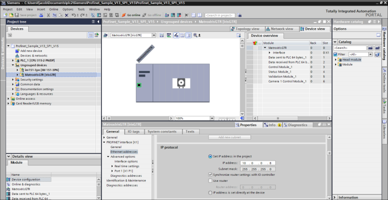
To configure the PLC to recognize your runtime platform as a slave device when using the PROFINET industrial communication protocol, you must use the Siemens Totally Integrated Automation (TIA) Portal software to assign the runtime platform's PROFINET interface a static IP address that is compatible with the automation network.
The general purpose NIC interface must also have a static IP address (set up using normal operating system settings); otherwise, the Auto-IP or DHCP modes might lead to the connection failing when the general purpose NIC interface attempts to discover a DHCP server or renegotiate its IP address.
Both the PROFINET interface and the general purpose NIC interface must be on the same subnet to run the Siemens TIA Portal software. The IP addresses of both interfaces must be unique on your network; otherwise, they will interfere with each other. To verify that there is no conflict, access the Communication page in the MILConfig utility and click on the PROFINET page. If there is a conflict, change either the general purpose NIC's IP address in the operating system settings, or change the PROFINET interface's IP address using the Siemens TIA portal software.
You should not enable the PROFINET service on a computer that has both the Siemens TIA Portal software and Matrox Design Assistant installed; this can cause network adapter addressing conflicts.
Configuring the
PLC
Data tables in
PROFINET
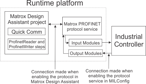
Matrox Design Assistant data tables correspond to modules in PROFINET. Each module is assigned a specific slot number. When the PROFINET protocol is enabled in Matrox Design Assistant, the DataToPLC and DataFromPLC pages, accessible from the Industrial Protocols page in the Platform Configuration dialog, list the application-specific data fields with input (I) and output (Q) designations next to their address, followed by the size of the data type chosen (for example, I, IB, IW, & ID). These designations are from the perspective of the PLC; when the PLC receives data, it reads it from an input field, and when data is sent by the PLC, it stores it in an output field. The Profinet page in the Platform Configuration dialog provides access to predefined Quick Comm slots and fields, as well as user-defined fields. Slots 3 and 4 are used for Control and Status. Slots 6 and higher are allocated one per physical camera shown on the Cameras page of the Platform Configuration dialog. The DataToPLC and DataFromPLC pages are used to manage additional data fields in slots 1 and 2, respectively.
The diagram below displays an overview of PROFINET communication, including the 2 levels of enabling required with a PLC.