
Events and actions
The recommended structure of a project is for the main flowchart to only contain the main inspection loop, which is the part that actively inspects images. You should place all other actions, such as configuration and recipe selection, in subflowcharts that will be called on operator view or PLC events. Common actions, such as operator view publishing, PLC handshakes, output resets, variable resets, and internal annotation buffer clearing, can also be handled automatically as background activity not requiring flowchart steps. For instance, PLC communication actions are event-driven when Quick Comm is enabled. Such event-driven architecture means that the main flowchart need not continuously poll (check) for requests from the operator view or changes in incoming PLC data, as was the case for legacy projects. Event-driven projects can therefore be designed more efficiently.
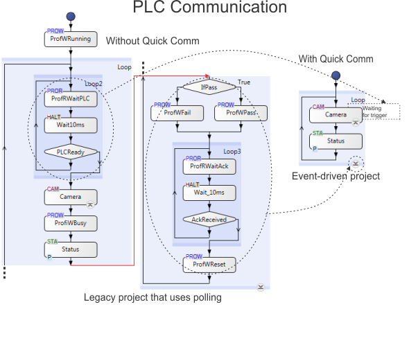
Note that legacy projects needed extra steps to poll for input changes. This is still the case for projects waiting for value changes on serial port, discrete I/O , Modbus, and TCP/IP communication. Although this is no longer required for EtherNet/IP or PROFINET, such projects will function as before.
 Action points
Action points refer to specific points in the flowchart, when certain actions occur (such as operator view updates, PLC communication, and internal annotation buffer clearing). The main action points are inspection start and inspection end; however, you can add additional action points (for example, based on PLC fields).
Inspection
start and inspection end (main inspection loop)
The inspection start and inspection end action points typically mark the beginning and end of the main inspection. During this time, the project is actively inspecting (analyzing images), and in its main inspection loop.
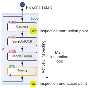
By default, the moment when the main flowchart fetches a new
image is considered to be the inspection start action point, and
the bottom of the main inspection loop is considered the inspection
end action point. These 2 action points are marked on the main
flowchart with circular arrowhead symbols showing the top
( )
of the inspection, and the bottom (
)
of the inspection, and the bottom ( ) of
the inspection. Clicking on one of these buttons lists the actions
that will take place when the point is reached. For information
about actions that can happen at the inspection end point when
using Quick Comm, see the
Status and control handshake subsection of the
Procedure for communicating with controllers section in
Chapter 41: Quick Comm protocol and PROFINET and EtherNet/IP
steps.
) of
the inspection. Clicking on one of these buttons lists the actions
that will take place when the point is reached. For information
about actions that can happen at the inspection end point when
using Quick Comm, see the
Status and control handshake subsection of the
Procedure for communicating with controllers section in
Chapter 41: Quick Comm protocol and PROFINET and EtherNet/IP
steps.
Adding other
action points
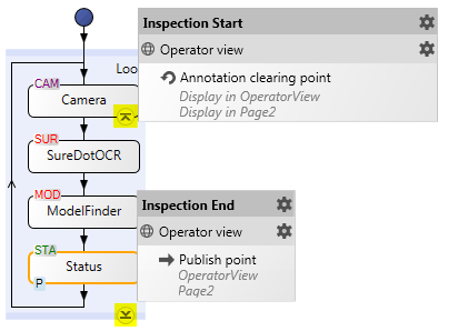
Flowcharts (including subflowcharts) can also have action points that are not inspection start or end. Such action points are indicated by similar arrowhead symbols and typically occur at the start (arrowhead pointing up) or end (arrowhead pointing down) of a step or subflowchart. A typical reason to add an action point is to explicitly update information in the operator view at the end of a subflowchart (by default, operator view publishing happens at the inspection end action point). To add such a point, use the Operator View Publishing Synchronization dialog, accessible from the Operator Views Synchronize publishing... menu item.
You can also define an action point to add an additional PLC handshake or send data. To add such a point, use the Actions page in the Platform Configuration dialog. Clicking the Add Action button allows you to place the action in the flowchart, (for example, OnPLCChanged (PassFailConditions) in the Matrox Design Assistant CodeReader template project).
To see the actions that will happen when the flowchart reaches an action point, click on the action point symbol.
Note that advanced users can add and modify action points that interact with industrial protocol data using the Actions page of the Industrial Protocols page in the Platform Configuration dialog. For an overview diagram of events and actions, see the Configuring actions and events section in Chapter 41: Quick Comm protocol and PROFINET and EtherNet/IP steps .
When actions
occur
Many types of actions occur during the course of a running project. Some actions are handled immediately, some are scheduled (synchronous), and some happen at unknown moments (asynchronous).
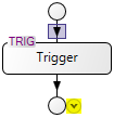
Acquisition trigger actions, along with any reset action triggered by a PLC reset request in the Quick Comm control section, are handled immediately. They are independent of action points.
Certain routine actions, such as updating the operator view (publishing) and Quick Comm handshaking, are scheduled to happen when the flowchart reaches their specified action points. Such actions always occur at the same points in the flowchart; they are called synchronous.
Changes in an
operator view input element (such as pressing a command button
or selecting a new value from a dropdown list), or events tied to
PLC field changes are asynchronous events, and can be
configured to execute a subflowchart. Such events typically occur
at unknown moments. These events cannot be handled while a project
is between inspection start and inspection end (actively
inspecting), and are queued until the inspection end action point.
At design-time, the
Events pending ( ) toolbar button in the
Platform toolbar, shows the number of events that are
queued.
) toolbar button in the
Platform toolbar, shows the number of events that are
queued.
Operator view
events
Types of actions
There are 3 types of event-driven actions:
For information about viewing a list of these actions, or executing these actions in your project at design-time, see the Testing event-driven actions subsection of the Testing and debugging a project section later in this chapter.
Operator view
publishing
PLC handshake
The PLC handshake actions are set, wait, and clear.
The set, wait, and clear actions are a key part of Quick Comm. The events that fire (trigger) these actions occur when the flowchart reaches an action point or when the PLC sets certain control bits. The basic Quick Comm handshake uses 6 bits, and optionally 1 trigger bit, per camera. You can also add Auto DataToPLC fields, from the Quick Watch flyout panel or from the Platform Configuration dialog; this will transfer the linked values of these fields at the inspection end action point. By default, a wait banner appears in the operator view if a running project is waiting for a handshake from the PLC.
For information about how to reorder and set data types for the fields, see Chapter 41: Quick Comm protocol and PROFINET and EtherNet/IP steps. For information about triggers and timers, see the Triggering section in Chapter 28: Acquisition and also see Chapter 40: IO steps.