With Matrox Design Assistant, you can create, manage, and
navigate between multiple operator views.
You can create more than one operator view for a project. The
typical use is to provide a view that is used by supervisory
personnel for changing key parameters or for training new
models.
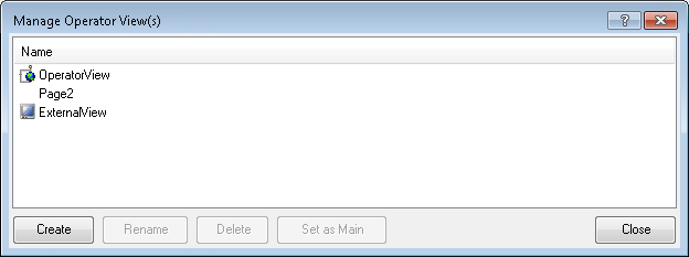
The Manage
Operator View(s) dialog in the Operator Views menu, shown
in the image below, allows you to create additional operator views.
These views include one view with a Filmstrip element, any number
of additional operator views without a Filmstrip element, and one
external view. You can also rename or delete existing views. The
operator view that is designated as Main is displayed when the
project starts running, and when a browser connects to the
project's operator view (for example, using a link).
The external view is output on the VGA connector of the
supported Matrox smart camera and contains a single image display
and, optionally, annotations. To configure the external view, you
must use the operator view layout set to ExternalDisplay.
The single image of the external view can be linked to any
project image. Annotations can be selected, and the display can be
restricted to a region of the image. The external view can be
"exclusive", occupying the whole desktop, or "windowed" allowing
the Start Menu, taskbar, and other desktop items to be
displayed.
When the ScaleImage property is
enabled, the image will be scaled to fit the size of the window, by
default. If disabled, then you can enter the initial zoom factor in
the Zoom
property. If the ZoomAndPan property is
enabled, regardless of how the zoom scale are initially set up,
then zooming and panning will be possible.
To zoom in the external view, you can either use the mouse wheel
or the '+' and '-' buttons to zoom, but you cannot use the right
mouse button to zoom as in the operator view Display element.
Note that when in the operator view layout or the Manage Operator View(s)
dialog, the term ExternalView applies to the display discussed
above, which is called the external display, and can only be
accessed through the supported Matrox smart camera. This has no
direct relation to the external display window accessed while in
the Flowchart, and applies to the image output of a single
step.
You can switch between operator views during design-time and
during runtime.

 During
design-time
During
design-time
To configure an operator view, select the operator view from the
list in the Operator
Views menu, found in the main menu. Then, set the properties in
the
Configuration pane.
During runtime
While the project is running, the user can switch to another
operator view using either of the following methods:
-
Use the Navigate step in
the flowchart.
The Navigate step's
Target property
specifies the operator view to which to switch. The Navigate step is
usually executed based on the value of a variable set by a button
in the operator view. This is the preferred method when different
operator view pages are associated with different modes or branches
of the flowchart (for example, a training mode and an inspection
mode).
The Navigate step can
also change which page is the default page to display when the
project is started. For example, a project that inspects one of
several different parts can have a different operator view page for
each part, and you might want the appropriate page to be displayed
even if the project is restarted. For more information, see the
Persistence subsection of the
Reconfigure step overview section in
Chapter 56: Reconfigure step.
-
Click on a button in the operator view whose Command property has been
set to Navigate.
This method is used when the alternate operator view page is not
tied to the flowchart's current mode (for example, the user might
access a statistics or log page without affecting the inspection).
When the operator view page is changed this way, the flowchart is
unaware that the operator view page has changed.
When you create a new operator view page, add a Button element.
In the
Configuration pane under the MANAGE ACTIONS page, check
Navigate Page
under the Operator View section. Select the newly created
NAVIGATE PAGE
tab, and set the Target property to the name
of another operator view page to display.
Note that switching between operator views requires a few
seconds.