Matrox Design Assistant X Version 1905
May 16, 2019
Copyright© 2007-2019 by Matrox Electronic Systems Ltd. All rights reserved.
Table of Contents
Third-party 3D sensor supports depth maps
Changes between DA5.x and DA4.0
2. New Installation of Matrox Design Assistant
2a. Prerequisites for the PC version
Upgrading Projects from a previous version of Design Assistant
4. Documentation, examples and tutorials
NOTE: DA X may be installed “side by side” with DA 5.1 or 5.0 on a PC. Use the Design Assistant Runtime Manager from the MIL Control Center to select which version of the localhost runtime will be active (only one runtime can be active at a time). If running PROFINET communication from a PC with both DA X Version 1905 and DA 5.1 runtimes installed, a DA5.1 Update 10 is required.
1. What’s New in DA X
For more details on what is new in Design Assistant X Version 1905 refer to Introduction to Design Assistant X, available as a pdf file in the Documentation folder and in the appendix of the User Guide.
New steps:
- CircleFinder, EllipseFinder, RectangleFInder and SegmentFinder
- PhotometricStereo
- CNNClassIndex
- CodeGrade (the legacy CodeVerify custom step can be replaced or upgraded)
- The Add step dialog has been reorganized by functional groups.
Processing changes:
- Modelfinder runtime reconfiguration of DXF models
- ModelFinder and PatternMatch – added ModelFInder edgel annotations (model and target) to Operator View and ImageWriter. Added editable annotation for ReferencePoint editing (note –this affects existing Reconfigure operations on the reference point).
- ModelFinder and PatternMatch and other steps with Regions – Reconfigure can now change the Shape of the region, including switching between WholeImage and Rectangle. No longer necessary to Clone a model to get a Search Region – though cloning is still a good way to start with appropriate settings if the defaults are not suitable for your image.
- ImageProcessing threshold and window levelling improved initial values and support for Z scale calibration
Image Object changes:
- High bit depth intensity images (e.g. 16 bit images from thermographic cameras) now automatically display using the Autoscale mode.
- Additional colormaps, independent colormap per images for steps with multiple output images
- Image outputs now include images statistics (min, max, mean, etc.) and pixel calibration factors (x,y,z if applicable)
Project and Platform changes:
- New project dialog offers choice of camera type, including supported third party 3D sensors (see below)
- Multiple runtime support:
o More than one DA project may run on a platform, as long as the projects have different names, and do not make conflicting resource requests (e.g. I/O pins)
o More than one project can be selected to start automatically on system boot
o Portal Pages have been restructured to accommodate multiple running projects.
- Industrial Communications:
o PROFINET
§ only supported on platforms with hardware assisted PROFINET – IrisGTR, 4Sight GPm, Indio, etc.. Software only mode has been discontinued (not certifiable)
§ GSD files – now one file per platform (IrisGTR, GPm, Indio), located under MatroxImaging\Config, and CameraControl modules start at Slot 6 instead of Slot 7
Recipes:
- Recipe handling has been optimised in design time. Only one recipe is loaded when the project is loaded. The Recipes pane has a new layout.
- Only variables that are “persist per recipe” appear in the recipe pane. Globally persistent variables only appear in the Manage Variables dialog.
Operator View
- Added direct binding of Operator Input elements and links to platform component inputs (for example camera exposure).
- Step Inputs that are bound to the operator view have a “B” tag next to them in the step configuration pane
- Added multi-language support, sometimes called localization. The developer creates a separate file for each language. The Portal Page displays a drop list to select the current language. A Tutorial in the Quick Start page provides information on how to implement localization of the Operator View.
- Added an editable annotation for interactively reconfiguring model reference points
Third-party 3D sensor supports depth maps
Added platform interface components for Photoneo PhoXi 3D camera, LMI Gocator line profilers, wenglor weCat3D sensors and Zivid One cameras.
· The third party 3D sensor interface acquires the output data from the 3D sensor’s API/SDK including range, intensity and confidence components and makes the data available to the camera step.
· Support for these devices is integrated into the New Project dialog Camera Type parameter and into the Platform Configuration PhysicalCamera dialog to specify Allocation Mode, API version and Trigger mode if available.
· Setup and configuration of the device is done using the manufacturers interface software.
· In the Documentation folder, added setup guides: e.g. Photoneo PhoXi with Matrox Design Assistant.pdf for each of the supported types. The Open Documentation button in the Platform Configuration dialog also links to the guides.
· A 3D MIL runtime license is required to use the 3D capabilities in a deployed project.
Camera step:
· Support for depth map images with new tabs.
o Gap filling methods for invalid data points.
o Generation of 8 and 16 bit integer remapped images allowing other DA steps to process depth map images.
o Additional Output Camera.DepthMap.
ImageWriter step:
· Option to save all the components of a depth map, or to save individual components.
· Image Sets automatically recognize depth map data sets.
· Project Change Validation records and verifies depth map data sets.
Display view
· Depth map images produced by 3D sensors are generally 16 or 32 bits deep, and are best viewed with a color map. A “Jet” multi-hued color map is used by default for depth map images. Using the right mouse menu in the display, other colormaps may be selected.
Calibration
· Range images produced by 3D sensors are typically in real world units (for example millimeters). The calibrated depth information (i.e., Z) is respected by Design Assistant.
· Step inputs that are usually in intensity units (e.g. threshold levels) are entered in Z world units when operating on a depth map.
· Cursor coordinates, line profiles and histograms report Z values.
· A function TRANSFORMZ is provided for situations where a conversion between world coordinates and image pixel values is required.
Changes between DA5.x and DA4.0
Design Assistant 5.0 introduced a wide variety of new features including recipes, templates, events and Quick Comm. DA 5.1 introduced the Project Change Validator, support for the Matrox Indio card, as well as a number of other improvements. We recommend the “Introduction to Design Assistant 5.pdf” document for full details. It is found in {installation path}\Matrox Imaging\DA 5.0\Documentation.
2. New Installation of Matrox Design Assistant
NOTE 1: You must have a copy of the Design Assistant setup that is local to the PC on which you are installing. Place the setup in a folder with a short pathname (e.g. C:\DASetup). Some components cannot be installed from a network drive (such as, the Matrox GigE Vision driver).
NOTE 2: If you need to, you can have Design Assistant 4.0 SP2, 5.0, 5.1 and X on the same development computer.
Since versions 4, 5 and X are based on MIL 10, they can be installed side by side.
[version 4 minimum SP1 required, but SP2 recommended (that is, build 820 or higher)].
However, only one version of the runtime (e.g. localhost) can be active at a time. Use the DesignAssistantRuntimeManager utility to specify the active version. Access the utility from the most recent Design Assistant Tools link in MIL Control Center.
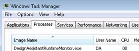
IMPORTANT when installing on a Matrox 4Sight GPm: After installing Design Assistant, the next reboot may start a firmware (FPGA) upgrade. If you get a message telling you that DesignAssistantRuntimeMonitor is using MIL, then you must use the Task Manager to kill the DesignAssistantRuntimeMonitor process so that the upgrade can continue.
2a. Prerequisites for the PC version
· 64-bit Windows 7 with SP1 or Windows 10 (Version 1607 to 1809)
· Internet Explorer 11 (Update 15 or higher) is required when deploying. An HTML5-enabled browser such as Chrome or Firefox can be used to view Portal Pages and Operator Views. If your Internet Explorer is not sufficiently up to date, you may need to apply an update such as kb3008923 for Windows 7.
· Has sufficient free hard disk space.
· ~ 3 GB (Design-time + Run-time)
· ~ 2.1 MB (Run-time only)
· If the .NET framework and other required Microsoft redistributables need to be installed, another ~160MB might be required.
· A processor that supports the SSE2 instruction set.
· Installation requires an administrative user account.
· If you are using GigE Vision cameras, sufficient Network Interface Controllers (NICs), that support Jumbo packets, to handle the bandwidth of your cameras. (Configuration information found in the CaptureAssistantHelp.pdf. It is found in {installation path}\Matrox Imaging\Tools.)
.NET Framework 4.7.1
NOTE: Design Assistant X requires .NET Framework 4.7.1. Microsoft .NET Framework installation on Windows 7 will verify the Trusted Root Certificate using the Internet. Ensure that the system on which you are installing has Internet access.
If that is not possible, you can acquire the appropriate Certificates by applying one or more Microsoft KB updates.
For Windows 7 (x64) SP1 you can use kb3149737 (Trusted Root Certification Authorities).
2b. Install Design Assistant
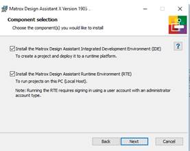
Run DesignAssistantSetup.exe to install Design Assistant.
The first two options (i.e., IDE and RTE) are typically both selected for your development PC.
Selecting only the second option (i.e., only RTE), is used when setting up a PC that will be deployed in the field without the Design Assistant design time environment.
3. Upgrading
Upgrading Matrox IrisGTR
IMPORTANT –Upgrading the Matrox IrisGTR will erase all content on the camera. Refer to the document “Matrox IrisGTR Upgrade Procedure.pdf” for information on backing up recipes and Project Change Validation sets.
The IrisGTR operating system (MIOS) and Design Assistant runtime environment are upgraded together from an .iso file. Generally this is done when Design Assistant tries to connect to an IrisGTR with a different version, or explicitly through the Platform IrisGTR Reset Camera Contents menu command.
IMPORTANT – The upgrade may also require upgrading the BIOS. Refer to the document “Matrox IrisGTR Upgrade Procedure.pdf” for BIOS upgrade instructions.
Upgrading Projects from a previous version of Design Assistant
· General information
· It is highly recommended to make a backup copy of your project before upgrading it to this new version of Design Assistant.
· Changes to Design Assistant X that could affect upgraded projects.
· The majority of the required changes will be done automatically.
· Pay particular attention if your project uses MODBUS communication, EtherNet/IP communication, PROFINET communication – you will have to define Instances of the communication protocol in MilConfig and select them in the project’s platform configuration dialog.
· There are a series of upgrade documents. These documents are found in the User Guide Readme appendix and via the Documentation link in MIL Control
Upgrading from DA 5.x to Design Assistant X.pdf.
Upgrading from Design Assistant 4.0 to 5.0.pdf.
4. Documentation, examples and tutorials
· Documentation
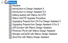
This Readme and other introductory material is available in the Documentation folder and as an appendix to the User Guide
- Context sensitive instructions are available at all times via the QuickAccess pane of the Design Assistant application.
The Matrox Design Assistant User Guide describes how to use the application and provides procedures for configuring the various steps. Click on an item that you want more information on, and press F1. The User Guide is also accessible from the MIL Control Center and from the Design Assistant Help Menu.
The Matrox Iris GTR with Design Assistant Installation and Technical Reference manual, IrisGTR.pdf, is provided in the Documentation folder accessible from the MIL Control Center.
· Tutorials
These are available from the Quick Start pages. Also the Matrox Vision Academy provides access to a wide range of training videos.
· Example flowchart projects
These are available from the Quick Start pages.
· Example HMI .NET projects (OperatorAPI)
These are available from the Quick Start HMI page.
· Example custom steps .NET projects
These are available from the Quick Start Custom Steps page.
· Location of example projects
C:\Users\Public\Documents\Matrox Imaging\DA 6.0
5. Limitations
For Design Assistant X Version 1905
5a. All Platforms
· When a project is deployed, an Internet Explorer browser is opened. Other browsers (such as, Chrome or Firefox) can be used with the Design Assistant Portal pages and when opening Operator Views directly.
o The Microsoft Edge browser is not supported.
o Requires a reasonably up to date Internet Explorer 11. (The RTM version may cause errors)
o By default Internet Explorer 11 limits the number of websockets to 6. Hosting a DA operator view requires more. The Design Assistant installation automatically increases this limit. However, if you access a Design Assistant operator view from a computer that does not have DA installed on it, an error will appear in the browser and you will be prompted to accept a change to a registry key to increase the limit.
· A standard user (not in Administrators group) can run the Design Assistant IDE in Emulation mode or connected to a remote platform. Standard users cannot run a localhost runtime, and should use the DARuntimeManager utility to disable the runtime environment.
· SureDotOCR font file names must begin with a letter, not a number, or they will appear truncated to the first letter.
· Do not use direct binding from operator view elements to StringReader step CharacterConstraints – these inputs are not “linkable” and trying to bind may cause the project to be unloadable.
· Custom step development for deployment to a Windows platform requires the Targeting Pack for .NET 4.7.1. This is an installation option for Visual Studio 2017 (recommended). If you do not have the Targeting Pack installed, you can get it from the Internet or in the CustomSteps\DotNetFrameworkDeveloper folder of your Design Assistant installation media.
5b. Iris GTR Platform
· When upgrading the BIOS of an IrisGTR smart camera, in the rare circumstance that you receive a message “Error: file offset + size...”, enter the command to run the .bin again. Refer to section 3. Upgrading and to the document “Matrox IrisGTR Upgrade Procedure.pdf”.
· The Hardware Installation and Technical Reference manual “IrisGTR.pdf” is included. The most recent version can be downloaded from the Matrox Imaging website, http://www.matrox.com/imaging/en/products/smart_cameras/iris-gtr/manuals/.
· Additional information is provided in the “Getting started with Matrox Iris GTR.pdf” document
· A serial port adapter to USB is not supported for SerialPort steps, but is supported for MODBUS/RTU.
5c. Indio System
· To successfully enable the EtherNet/IP industrial protocol on the GigE port of the Indio, an Ethernet cable must be connected to the Ethernet output connector and the Network Adapter must not be in Link-Local (Auto-configure) mode. Typically, it should be in static addressing mode.
6. Troubleshooting
· Microsoft Windows Issues
· Error 8013141c Cryptographic failure while signing assembly. This problem may appear after a Windows Upgrade. This error prevents links inside DA projects from working and prevents deployment of projects.
· Solution A –
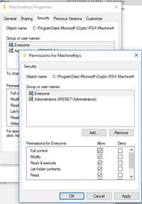
- Go to %programdata%\Microsoft\Crypto\RSA (different path for Windows 7)
- Right click on MachineKeys, select Properties. Select the Security tab
- Select ‘Everyone’ as the user
- Click on Edit
- Select Allow full control
- Click Apply, then OK
-
· Solution B– Alternately, set the properties of Design Assistant.exe to run “as an Administrator”.
· Cause: This error occurs when the user account cannot access the Microsoft\Crypto\RSA\MachineKeys folder
The folder is found in different locations
· Windows 7: C:\Documents and Settings\All Users\Application Data
· Windows 10: C:\ProgramData
· Troubleshooting with Matrox Iris GTR.
· See the “Getting started with GTR.pdf” document for full details. It is found in the Documentation folder and as an appendix to the User Guide.
· Troubleshooting with PC platforms with GigE Vision or USB3 Vision
· Refer to Appendix C: Troubleshooting in the User Guide
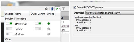
· Troubleshooting Hardware-Assisted Profinet
· If the Profinet option is greyed out in the Comm menu even though the protocol is enabled in MilConfig > Communications > Profinet page, and no address values appear on that page, try the following: Uncheck enable in Milconfig and click Apply. Recheck enable and click Apply. Two addresses should appear.
· Getting assistance
· If it is necessary to seek assistance from Matrox Imaging Technical Support, it is important to generate an information log.
· From MIL Control Center, run MILConfig, select Troubleshooting and then Start log.
· The MILConfig utility will collect information from your PC and from the last connected runtime platform, if it is reachable.
7. Licensing Notes
Files to comply with section 3A of the Microsoft Reciprocal License (Ms-RL) for WPF Dynamic Data Display are found at https://ftp.matrox.com/pub/imaging/designassistant/Dynamic_Data_Display_Source_Code.zip