Connecting to your Matrox Iris GTR as your runtime platform
 Previous
- Next

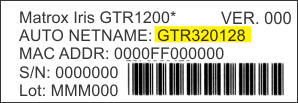
To connect to your Matrox Iris GTR as your runtime platform, use the Connect Remote link on the Quick Start tab when you first launch Matrox Design Assistant, or the Platform Connect remote menu item. This opens a dialog that prompts for the network name of your Matrox Iris GTR camera or its IP address. The default network name (AutoNetName) is written on a sticker on the smart camera.
Note that Matrox Iris GTR uses DHCP by default. If your network does not use DHCP, see the Configuring Matrox Iris GTR for static IP addressing subsection of the Using the Matrox Iris GTR desktop section later in this chapter.
While connecting, Matrox Design Assistant verifies the version of the firmware on your Matrox supported smart camera, and guides you through any necessary updates. Matrox Design Assistant can connect to Matrox Iris GTR runtime of the same major version with an equal or lower build number.
Once Matrox Design Assistant establishes a connection with your Matrox Iris GTR smart camera, the New Project and Open Project links become available in the Quick Start tab and the name of the connected Matrox Iris GTR appears at the top of the window. You can also find these options through the File menu.
For more information on connecting to a platform, see the Connecting to a runtime platform section in Chapter 2: Building a project.
 More information
Acquisition
overview
Platform
settings for your camera
Your supported Matrox smart camera's settings differ slightly from those of a GigE Vision or USB3 Vision camera. You can access the physical camera page from the Cameras page in the Platform Configuration dialog.
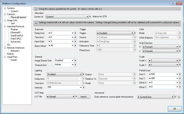
Note that, in emulation mode, some inputs will be unavailable, but many more will be set to Camera. Names of camera inputs can differ between different supported GigE Vision/USB3 Vision cameras and supported Matrox smart cameras.
The physical camera page in the Cameras page has additional sections and information when connected to a Matrox Iris GTR:
|
Section name |
Description |
|
|
Exposure |
Specifies the general camera settings relating to the exposure. |
|
|
Input |
Description |
|
|
Delay |
Specifies a period of time to delay the start of the exposure, in msec. When set to 0, the exposure immediately follows the trigger (this is your supported Matrox smart camera's default behavior). |
|
|
Time |
Specifies the duration of the exposure period (following the optional exposure delay), in msec. |
|
|
Input gain |
Amplifies the video signal by a specified factor, which can make the captured image appear brighter. It can also amplify the noise present in the image. With a short exposure, you might need to set Input gain to a higher value to improve your results. |
|
|
Black Offset |
Specifies the offset to the black level of the image in the camera. Essentially, this offset is subtracted from the pixel value of the image before it is stored in memory. A low black offset will give a brighter image while a higher black offset will give a darker image. |
|
|
Note that Input gain, Exposure, and Black Offset settings vary between the different models of smart cameras (for example, between Matrox Iris GTR300 and Matrox Iris GTR2000). When creating a new project, Matrox Design Assistant inquires these settings from your Matrox Iris GTR and can explicitly set these values for the smart camera you are using. When running this project on another model of smart camera, there might be inconsistencies. To create a project that will run correctly on various smart cameras, select the Default item for Input gain, Exposure time, and Timeout. Default settings; these will use the camera-specific values each time the project is deployed to a new Matrox Iris GTR. |
||
|
Trigger |
Specifies whether triggered grab mode is enabled in your project. For more information on triggering possibilities, see the Triggering section in Chapter 28: Acquisition. There is one additional field to this section: |
|
|
Input |
Description |
|
|
Debounce |
Specifies the amount of time (in nsec) that, after detecting a valid trigger input signal edge, any other transitions are considered noise and are suppressed. This is useful when using mechanical trigger switches. With Matrox Iris GTR, a debounce time of at least 10000 nsec is recommended. |
|
|
Grab direction |
Specifies that the grab occurs from left to right (forward) or from right to left (backward). |
|
|
Lighting |
Specifies the strobe settings from your camera. For more information, see the Lighting control from the camera subsection of the Grab and auxiliary I/O overview section later in this chapter. |
|
|
Partial scan |
Specifies changes to the size of the grabbed image area (allowing the smart camera to perform a partial scan). The specified offset relates to the top-left corner of the scanned area within the full image. |
|
|
LUT Map |
Specifies the name of the file containing a lookup table (LUT) to use to map the pixel values of grabbed images before saving to memory (a point-to-point LUT mapping operation). Note that, to use this file, you must click on the Import button in the Cameras page. In most situations, the same effect can be achieved with an ImageProcessing step, see the LutMap subsection of the ImageProcessing step operations section in Chapter 9: ImageProcessing step. To create the file, use MIL. Allocate a buffer with the M_LUT attribute and then save the buffer to a file. By default, this file will have an extension of LUT. |
|
|
Advanced |
Specifies the grab reference source. When a software trigger is enabled, the source for the trigger can be the system clock, an I/O Command List, or a I/O Command List latch. For information about I/O Command Lists, see the Matrox Advanced I/O Engine section in Chapter 40: IO steps. |
|
Note that when a project is running on your Matrox Iris GTR, the
values in the
Platform Configuration dialog are grayed-out or disabled.
Use the
Stop project ( ) toolbar button in the
Platform toolbar to stop the project if you want to change
the settings.
) toolbar button in the
Platform toolbar to stop the project if you want to change
the settings.
For more information on your camera, see the Platform settings for your camera section in Chapter 28: Acquisition.