ImageProcessing step operations
Related image processing operations are grouped together into the following categories:
 Filtering
Filtering operations are used to remove noise, emphasize edges, or calculate the strength of edges. There are 9 simple Finite Impulse Response (FIR), 2 multi-purpose Infinite Impulse Response (IIR) filters, a Rank filter and the UserKernel operation.
The following provides a basic methodology for using filtering operations.
-
Specify the source image. Optionally specify a second source image if the operation requires it.
-
You can specify a Region to only work on a portion of the image.
-
To control the behavior at the boundaries of a region you can enable Overscan to consider neighboring pixels even if they are outside the region.
Sharpening, smoothing,
and edge detection
IIR filters
FIR filters
User-defined
kernels
Arithmetic
Logic
Geometric
Threshold
PolarTransform
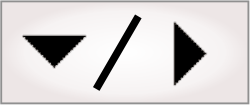
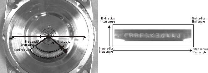
The RectangularToPolar operation unwraps a circular ring or sector of the image into a rectangular image. This might be used to perform character recognition, for example, with the StringReader step (for more information see Chapter 19: StringReader step), on text that is wrapped around a circle.
-
Specify the source image.
-
Define the circular sector in the SourceImage display by clicking on the Specify button. Set the region by drawing a ring sector by clicking on 5 points in the image.
-
The first click is the center. The second and third clicks define the 2 radii. The second click will end up at the bottom of the rectangle and the third click at the top. The 4th and 5th clicks define the start and end angle. The scan will be counter-clockwise from the start angle, but can be changed.
-
-
The Escape key allows you to start over.
-
Alternatively, you can also specify the sector region by specifying the Center, Radius, and Angle values.
-
Specify the sweeping Direction to Clockwise or Counterclockwise.
-
Specify the Interpolation mode if a smoother approximation is needed. NearestNeighbor is the default.
If you are unwrapping a large circle and the outer circumference is longer than the width of the OutputImage, you must increase its Width appropriately.
LutMap
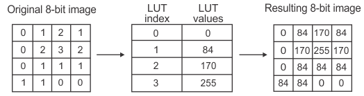
A lookup table mapping (LutMap operation) will replace each pixel value with a precalculated value at the corresponding table index. Using LUTs can easily reduce a multi-step or complex operation to a single-step LUT mapping. LutMap operations include WindowLeveling and UserLut. The following image demonstrates how a LUT is used:
WindowLeveling is a mapping that takes a range of source image values and stretches or compresses them to fit between an output range. To set the Input range and the Output range, you can use the sliders or enter a value or expression. Note that pixel values outside the input range will be mapped to the minimum and maximum values of the output range. WindowLeveling is useful for increasing contrast and for converting data to a different pixel depth (for example, mapping 0-1023 down to 0-255). See the Improving contrast subsection of the Common tasks using the ImageProcessing step section earlier in this chapter for an example on how you can use the WindowLeveling operation.
UserLUT allows you to import the mapping from a file that has been created with the Matrox Imaging Library and has the attribute M_LUT. Alternatively, you can pass an array with LUT values generated from an expression.
The following provides a basic methodology for using the UserLut operation.
-
Specify the source image to map. Specify a region if you want to work on a portion of the image.
-
Select the Import a file option if you are importing a pregenerated LUT from a file. Otherwise, select the Define an array option and use the RANGE or REPEAT functions in the Advanced editor to generate a LUT.
The following example uses the RANGE function to generate a LUT. In this case, the SELECT function then applies a POWER function expression to each element of the LUT to perform gamma correction.
Note that the gamma value is typically between 0.5 and 3.
Copy and Convert
Color
The color category allows you to perform distance and projection operations.
Distance
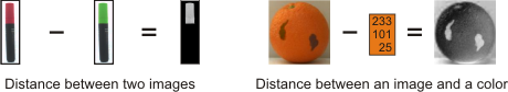
You can calculate the point-to-point distance (difference) between 2 images or between an image and a specific color using the Distance operation. Calculating the color distance can be useful to, for example, identify regions of interest or to find flaws.
The following provides a basic methodology for using the Distance operation.
-
Click on the Add button from the Configuration pane and select Distance from the Color category.
-
Specify a 3-band image as the source image (Source 1).
-
Specify whether to compare the source image to another image or to a color.
-
Set the type of distance calculation to Euclidean, Manhattan, or Mahalanobis.
A Euclidean distance type is a standard color distance that is typically sufficient, particularly for RGB. For HSL, you should use a Manhattan distance. A Mahalanobis distance is generally the slowest, though most robust, type of distance calculation and is usually suited for elongated colors. For more information, see the Color distance subsection of the ColorMatcher step advanced concepts section in Chapter 11: ColorMatcher step.
-
Optionally, normalize (remap) distances according to the greatest calculated distance. In certain cases, this can help distinguish the distance between similar colors. For more information, see the Distance normalization subsection of the ColorMatcher step advanced concepts section in Chapter 11: ColorMatcher step.
Projection
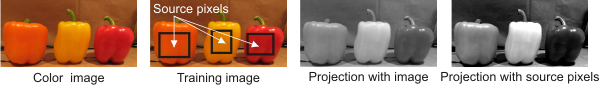
You can optimally convert a color image to grayscale using the Projection operation (principal component projection).
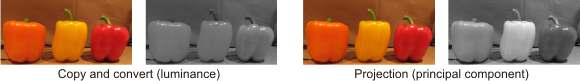
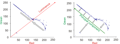
Unlike conversion with Copy and Convert, projection does not extract one color space component. Instead, it uses a training image to perform a principal component analysis (PCA) to calculate the color image's strongest vector (principal component), which is the line, within the color space, representing the greatest degree of color variation. Each color pixel is then projected to a point on this vector, which minimizes the loss of information and results in a grayscale image with a maximum amount of contrast, thereby better differentiating the colors in the original source image.
For optimal results, your color image should contain 2 principal colors. You can achieve good results if your image also contains a mixture of the 2 main colors.
The following provides a basic methodology for using the Projection operation.
-
Click on the Add button from the Configuration pane and select Projection from the Color category.
-
Display the image you want as the training image and click on the Set Training image button in the Project toolbar to set the current image as the training image. Typically, the training image is the same as the color image to convert (source 1). The training image determines the projection that will be applied to the source image, so the projection is not recalculated every time the step runs.
-
Optionally, click on the Mark source pixels button in the Project toolbar to identify the source pixels, in the training image, to use for calculating the principal component projection.
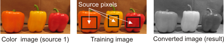
By default, the projection uses the whole training image. However, this can result in a less effective projection since all colors are considered, even those you are not interested in. This can be especially problematic if the image's background, which you typically want to ignore, is predominant.
-
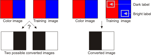
Optionally, click on the Mark bright/dark pixels button in the Project toolbar to identify the pixels, in the training image, that should correspond to the bright/dark pixels in the projection.
Typically, the colors are successfully projected between the brightest (white) and darkest (black) side of the grayscale palette. However, in some cases the projection cannot correctly determine this and the direction of the projection is arbitrary. In this case, you should identify the bright/dark pixels.
-
Optionally, select the pixel range with which to map the projection.
By default, the projection result is mapped according to the dynamic range of all the pixels in the source image, even if you identify the source pixels with which to calculate the principal component. If necessary, you can further improve the conversion to grayscale by mapping the projection according to the dynamic range of only the source image pixels. The result is similar to an increase in contrast.
When projecting with source pixels, the color image pixels that are outside the dynamic pixel range (for example, the background) might be saturated. In this case, the resulting image might not adequately represent the source image.