Collapse
CollapsingX
  • - or -

Procedure for using the BlobAnalysis step


The following procedure provides a basic methodology for using the BlobAnalysis step.

  1. Grab or load an image that was captured under the best possible conditions.

  2. Configure settings to fit your application.

  3. Apply Thresholding to use a binarized version of the image for identifying blobs.

  4. Select the features to calculate.

  5. Optionally, use Filters to exclude, include, or delete blobs that do not meet certain criteria.

  6. Optionally, use the results of the previous step as the input to another BlobAnalysis step to further analyze the previous step's results.

  7. Optionally, enable the creation of an output image.

Grab or load an image

The source image should be acquired under the best possible circumstances. This means ensuring that blobs do not overlap and, if possible, do not touch. It also means ensuring the best possible lighting and using a background with a gray level that is very distinct from the gray level of the blobs.

See Chapter 28: Acquisition for information about grabbing or loading an image.

Configure settings

Adjust the settings to control how the source image is processed. To modify the settings, perform the following:

  1. Set the Foreground value of the blobs. If your blobs are dark, set the input to Black. If your blobs are bright, select White.

  2. Draw the search region, if needed. To do so interactively, select this step in the flowchart and use the Define a region () toolbar button in the Project toolbar. See the Search regions section in Chapter 2: Building a project for more information.

    Note that you can click on the Search Region... button in the Configuration pane to manually enter values for the search region.

  3. Enable the Fill holes option to fill holes inside closed regions of foreground pixels in the search region. This option can be time and memory consuming on large images.

  4. Enable the Remove border blobs option to remove blobs that touch the borders of the search region. This option can be time and memory consuming on large images.

  5. Set the Threshold mode and value. By default, the threshold mode is Simple and the value is set to 85.

Thresholding

Typically, the BlobAnalysis step creates and works on a binarized version of the source image, known as the BlobIdentifierImage. In this binarized image, each pixel is set to one of 2 values (typically, black or white), depending on whether the source pixel's intensity is above or below a specified threshold. This allows for easier separation of foreground from background, and permits faster processing. You can choose from 2 different threshold modes when using the BlobAnalysis step: Simple and TwoLevels.

  • The Simple threshold mode sets all pixels with an intensity value below the Threshold low input to black; all other pixels are set to white. Use the slider to adjust the threshold, or enter a value in the text box. The Automatic Threshold option will automatically choose a threshold value. This option works best for images obtained with even lighting and when foreground objects are already distinguishable from background pixels.

  • The TwoLevels threshold mode sets all pixels with values between Threshold low and Threshold high to white. Pixels with values lower than Threshold low and higher than Threshold high are mapped to black. This mode is useful when the objects of interest are neither black nor white.

When working with depth maps, use a world Z-value (depth value) to set the Threshold. For more information on depth maps, see Chapter 38: Working with depth maps.

Select the features

Add the Features that you want to calculate. To do so, perform the following:

  1. In the Features section of the Configuration pane, click on the Add... button to add features.

  2. Choose the features you want to calculate.

For a list of the features and their description, see the BlobAnalysis step features section later in this chapter.

By default, blob results are presented in the order in which the algorithm found them. If, for example, you need to access the largest/smallest, roundest, brightest/darkest blob, you can define a sorting key. To do so, perform the following:

  1. Click on the Sorting... button to add sorting keys.

  2. Select the Enable option for a sorting key.

  3. Select a feature from the dropdown list.

  4. Select whether you want the results to be sorted in ascending or descending order.

  5. You can enable a second (and third) sorting key, but they are only used to distinguish between blobs that have an identical value in the preceding key(s); therefore, a second or third sorting key is only used when the previous sorting key uses a discrete quantity value like NumberOfHoles. Due to noise and discretization errors, positions and sizes of roughly identical objects might not give identical results.

Note that the columns in the blob result table can be re-ordered by clicking on the header of the column and dragging it to the required location.

Filters

You can Filter blobs based on their feature values. You can create a filter to exclude, include, or delete blobs based on criteria that you specify. The BlobAnalysis step has a default filter, ExcludeAreaLessThan20, which excludes blobs with an area of less than 20. Note that area is the number of foreground pixels in a blob (hole pixels are not counted).

To add a filter, perform the following:

  1. In the Filters section of the Configuration pane, click on the Add... button to define a new filter.

  2. Optionally, give a meaningful name to the filter (for example, ExcludeAreaLessThan5).

  3. Choose a filter Operation. The default is Exclude.

  4. Choose a Filter criterion. Create your own custom filter based on feature values, or select a predefined filter based on which image edge the blobs are touching or based on the blobs' current status.

  5. For a custom filter based on feature values, specify the Feature to evaluate as part of the blob selection, a Condition, and 1 or 2 numeric values that set the Low or High limit for the condition. For example, you can choose to exclude blobs whose areas are greater than the specified low value.

If you want to swap the blobs in the inclusion and exclusion list (that is, include the blobs currently excluded and exclude the blobs currently included), perform the following:

  1. Add a new filter and set its Operation to IncludeOnly.

  2. For the Filter criteria, choose Filter based on the current status of blobs and set the Status input to ExcludedBlobs.

This will put all the blobs into the exclusion list and only bring back into the inclusion list the blobs that meet the specified condition.

Use the results of the previous step

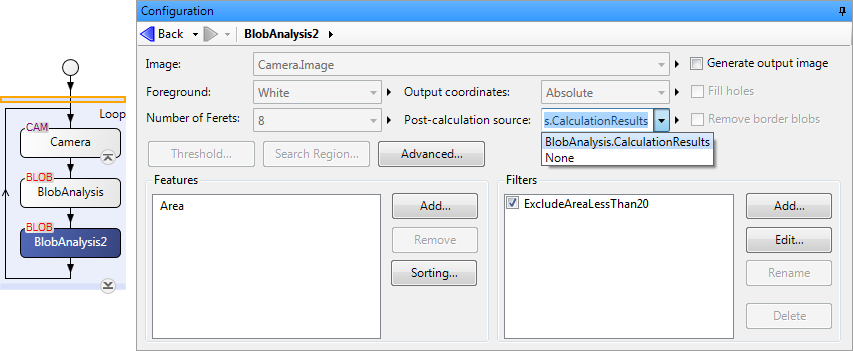
If you want to continue processing from the results of a previous BlobAnalysis step (for example, using the first to filter out certain blobs and using the second to analyze the ones that remain), set the second step's Post-calculation source input to the first step's CalculationResults.

When you specify a previous step's CalculationResults, you can add filters to reintroduce previously excluded blobs or exclude additional ones, as well as calculate additional features. Note that the Image, Foreground, Number of Ferets, Output coordinates, Fill holes, and Remove border blobs settings are disabled.

Creation of an output image

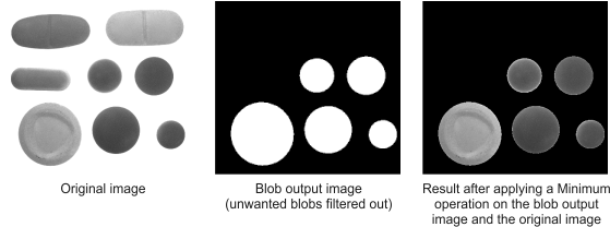
The BlobAnalysis step can create an image that contains all of the blobs found, or a subset of blobs with similar features. This output image can then be used as a mask for further image processing. For example, you can use an ImageProcessing step's Arithmetic Minimum or Maximum operation (depending on whether the blobs in the output image are white or black, respectively) to mask out everything except the required blobs in the original image.

To produce an output image, you must enable the Generate output image option in the BlobAnalysis step's Configuration pane. Once enabled, click on the Advanced button to customize settings for the output image. For example, you can set the gray level of the background and the blobs using the Background value input and Value input, respectively.

To see the output image, right-click on the display view and when the context menu appears, select Display Image and then OutputImage.

Using the Blobs to draw input, you can choose which subset of blobs to draw in the output image: all blobs, all blobs excluded by the filters, all blobs included by the filters, or labeled blobs. You can also choose to draw holes or convex hulls. Selecting DrawLabels will draw each blob in an incrementing gray value, starting with 1. If there are more than 255 blobs, set the Image type input to Unsigned16Bits.

Note that when you set the Blobs to draw input to DrawLabels, all blobs are drawn by default. To draw only the labeled blobs that pass a filter, set the filter's Operation input to Delete, instead of Exclude or ExcludeOnly. Your filter criteria should be based on unwanted features. For more information on filters, see the Filters subsection of this section.