BlobAnalysis step features
Calculations for features are performed on the blob identifier image. If the feature you want calculated requires a grayscale image (the feature contains Gray in its name), you need to specify the Gray image mode property to SourceImage, BlobIdentifierImage, or LinkedImage.
Additionally, features in the Statistics category also require a gray image.
 Area and
perimeter
Area and
perimeter
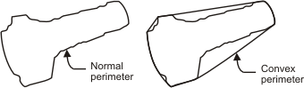
Some of the most common features you might want to calculate are the area and perimeter of a blob.
Calculating the Area will count the number of foreground pixels in a blob while discarding holes (background pixels) inside the blob.
The Perimeter is a measure of the total length of edges in a blob (including the edges of any holes). Whereas, the Convex Perimeter feature will calculate the perimeter of the convex hull:
Contact points
Feret dimensions
Besides the area, perimeter and blob points coordinates, you might want to calculate the dimension of the blobs. Since blobs are not always rectangular in shape, you will probably have to take the length of the blobs at various angles from the horizontal axis. This type of measure is often called an index caliper. This is actually one of the many definitions of the blob length, called the Feret diameter. For example, the following shows the Feret diameter of a blob taken at various angles.
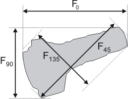
You can automatically determine the minimum, maximum, and average Feret diameters of the blob. These diameters will be determined by testing the diameter of the blobs at several angles.
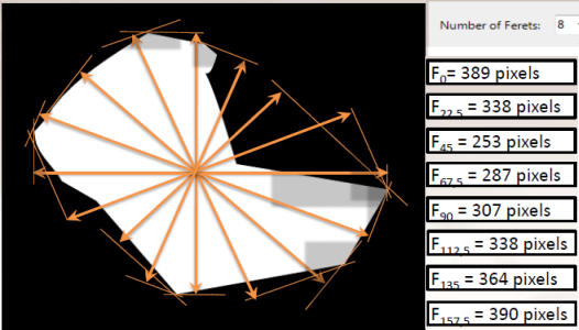
You can use the Number of Ferets property to change the number of angles; these angles will start at 0° and increase in increments of 180°/n , where n is the number of Feret diameters. The default value for this property is 8. Increasing the number of angles that are tested increases the accuracy of the results, but also increases processing time.
The following diagram illustrates Ferets. Note, the angle at which the Feret diameter is taken (relative to the horizontal axis) is specified as a subscript to the F.
Matrox Design Assistant provides several Feret measurements features you can calculate:
-
The maximum and minimum Feret angle and diameter.
-
The average Feret diameter for a specified number of Ferets. The default value is 8.
-
The dimensions of the minimum bounding box of a box in the horizontal or vertical direction.
-
The Feret at a specified angle.
-
The measure of the shape of a blob. That is, the maximum Feret diameter / minimum Feret diameter.
Included/Excluded
Shape
Determining the shape of a blob can be useful in the process of classifying blobs. For example, 2 blobs can have similar sizes, but different shapes because of a different number of holes, curves, or edges.

To distinguish shapes, Matrox Design Assistant provides a number of features that you can calculate. For example, if your application needs to differentiate a bolt from a nut, you can use the Number of Holes feature to count blob holes.
The features available are: Breadth, Compactness, Elongation, Euler Number, Length, Number of Holes, Number of Runs, and Roughness.