BlobAnalysis step advanced settings
Some of the advanced settings available for the BlobAnalysis step are:
-
the Connectivity subsection of this section.
-
the Gray image modes subsection of this section.
-
the Identification modes subsection of this section.
-
the Accessing BlobAnalysis step results section later in this chapter.
 Connectivity
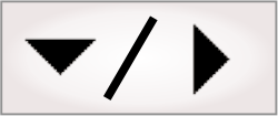
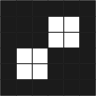
By default, Matrox Design Assistant considers all adjacent, touching, pixels as connected. This means that diagonally adjacent pixels are considered touching. However, if your blobs are separated by thin diagonal lines, you can set the Connectivity input to FourConnected to only consider adjacent pixels along the vertical or horizontal axis as touching.
For example, the following is considered one blob if Connectivity is set to EightConnected, but 2 blobs if set to FourConnected.
Gray image modes
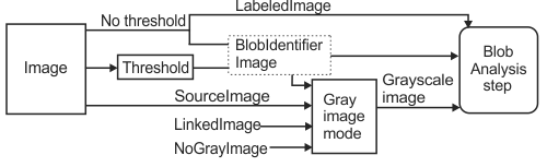
Some features require a gray image to calculate their results, for example Mean Pixel Value. To specify the image on which to perform the calculation, you can set Gray image mode to SourceImage, BlobIdentifierImage, or LinkedImage.
-
SourceImage is the image that is specified by the Image input.
-
BlobIdentifierImage is a copy of the source image which has been thresholded. For more information, see the Thresholding subsection of the Procedure for using the BlobAnalysis step section earlier in this chapter.
-
Select LinkedImage to use another image for grayscale feature calculations, for example the output image of an ImageProcessing step. Specify the image in the Gray image dropdown list.
Your project will not run if you set Gray image mode to NoGrayImage and have selected features that require a grayscale image.
The following illustration shows the types of images that you can apply to the BlobAnalysis step.
Identification
modes
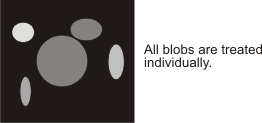
You can specify how Matrox Design Assistant will calculate the features of individual or groups of blobs by setting the Identification mode input.
When set to Individual, all blobs are measured individually without regards to their foreground pixel value.
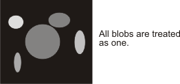
All blobs are grouped together and treated as one when set to WholeImage. In this case, calculating a feature such as Area will calculate the total area of all the blobs present in the image.
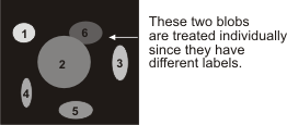
When set to Labeled, blobs with the same label will be grouped together. That is, all blobs with the same foreground pixel value will be treated as one disjoint blob.
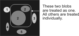
To treat touching blobs as distinct, set the Identification mode to LabeledTouching. With this mode, you can perform calculations on individual blobs even though they are touching, provided that each blob has a different label.
If the Identification mode is set to Labeled or LabeledTouching, set Thresholding to None.
Creating a
labeled blob image
To process and analyze blobs according to their label value (Identification mode set to Labeled or LabeledTouching), you must first manipulate the image so that each set of blobs that you want treated as one blob has a unique grayscale value.
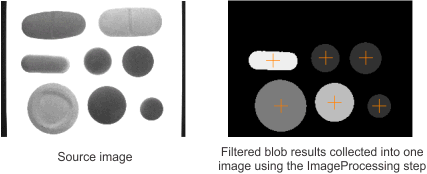
For example, you can collect multiple filtered results in the same output image, where all blobs are appropriately labeled. The general procedure is to add multiple BlobAnalysis steps to your flowchart and, at each step, generate an output image with a unique label applied to a blob subset. Then, use an ImageProcessing step to aggregate the labeled blobs in the different output images into one image.
The following procedure provides a basic methodology:
-
Add a BlobAnalysis step; configure the threshold and add filters to filter out unwanted blobs.
-
Enable Generate output image.
-
For the output image, assign a label (gray level) to the remaining included blobs. To do so, on the Advanced page, select DrawIncludedBlobs from the Blobs to draw dropdown list. Then, set a unique gray level for the blobs in the output image using the Value input.
Note that the Background value input must be set to 0. This will ensure a properly labeled final image.
-
Repeat steps 1-3 of this procedure to add a unique label to more blob subsets. If you want to label a subset of a previous set with a different label, set the Post-calculation source to CalculationResults. In this case, use a unique label value that is higher than the previous set's label.
-
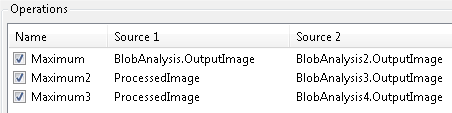
Add an ImageProcessing step. Add the Arithmetic operation Maximum as many times as necessary to accumulate all the filtered blobs into a single image. For the first maximum operation, set the 2 source images to 2 different BlobAnalysis output images. For subsequent maximum operations, set Source1 to ProcessedImage and Source2 to another BlobAnalysis output image.
-
All labeled blobs should now be visible in a single image.
-
You can add another BlobAnalysis step and set its Identification mode to Labeled or LabeledTouching to calculate features of your grouped blobs. Set the Image input to the OutputImage of the previous ImageProcessing step.