
Grab and auxiliary I/O overview
The acquisition hardware and the Matrox Advanced I/O Engine hardware of your Matrox Iris GTR are central to its functioning; configure them through the Cameras and IOs pages of the Platform Configuration dialog, respectively. In particular, the data and control paths connecting the various auxiliary input and output signals can only be set up from the Platform Configuration dialog and therefore remain fixed for the duration of the project.
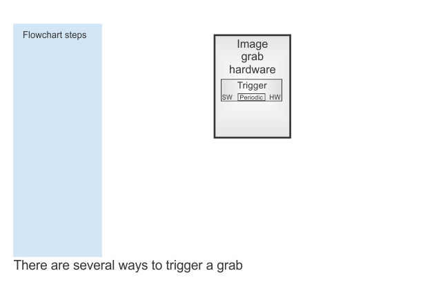
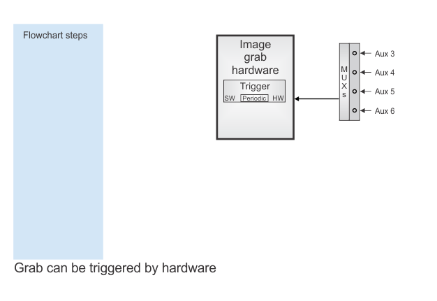
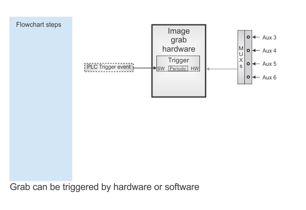
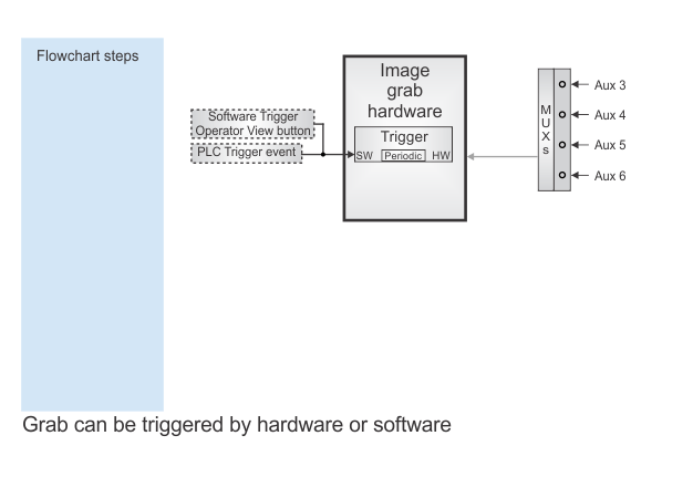
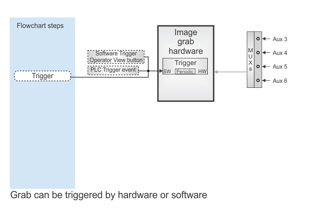
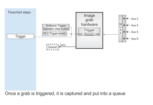
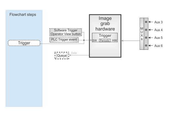
Grabs can be triggered in several ways (such as, through an auxiliary input signal, an operator view button, or a software trigger signal via a PLC or Trigger step). For more information, see the Triggering from a hardware signal subsection of the Triggering section in Chapter 28: Acquisition.
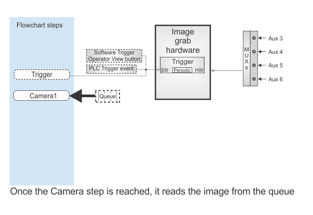
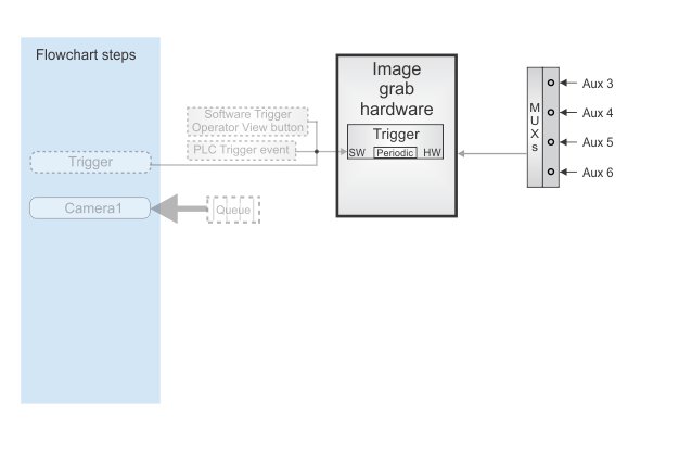
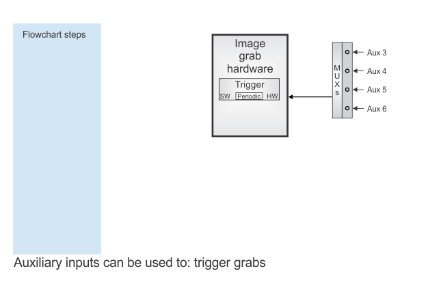
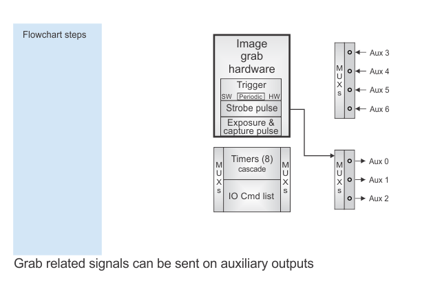
The following animation describes various aspects of working with the auxiliary I/O features of your Matrox Iris GTR.
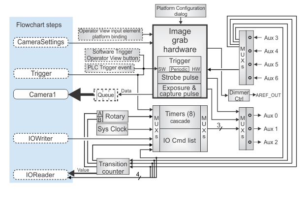
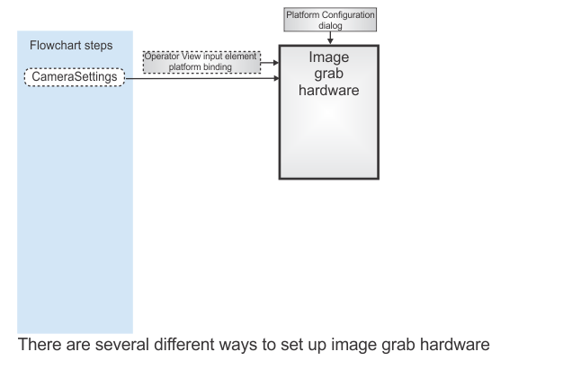
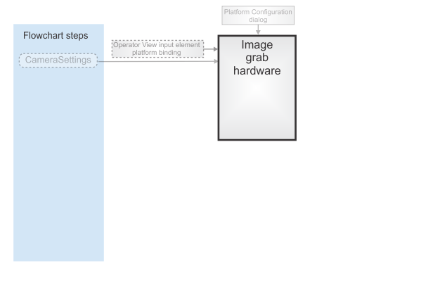
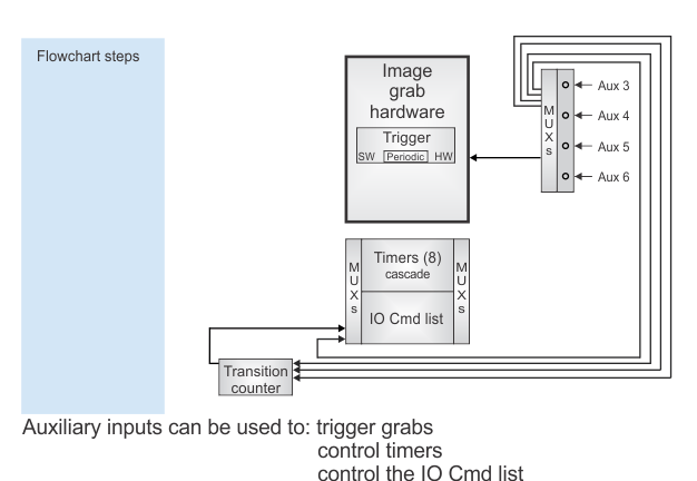
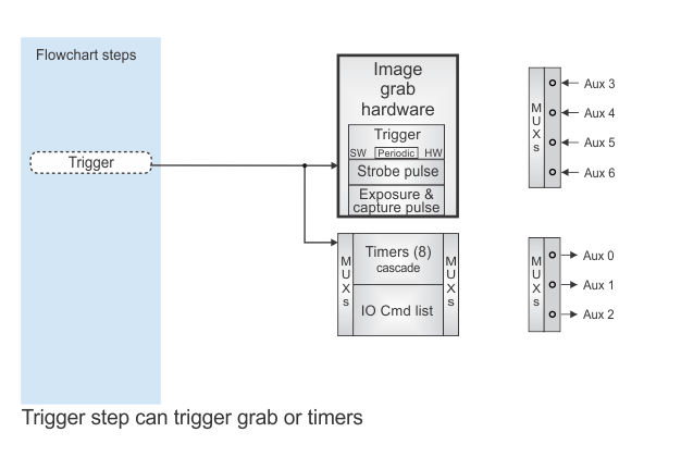
While the flowchart is executing, the flowchart can make changes to data values, the duration of some signals, and control both the triggering of the grab and timers. These changes are performed using the following steps: the CameraSettings step, Trigger step, IOWriter step, and TimerSettings step.
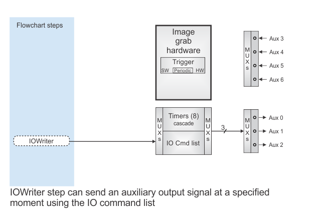
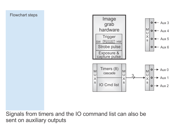
The IOWriter step sends a signal to the smart camera's I/O command list, which is then sent out to the specified auxiliary output signal (one of 3).
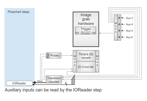
The IOReader step receives and reads all the auxiliary input signals and, if enabled, the transition counters. Both the IOReader step and IOWriter step are described further in the Procedure for using the I/O steps section in Chapter 40: IO steps.
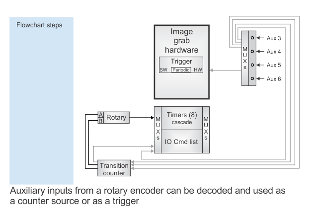
Alternatively, you can route the auxiliary input signals to the Advanced I/O Engine; which includes rotary decoders, timers, and latches. For more information, see the Communication with Matrox Iris GTR section later in this chapter.
Similar settings can also be changed from the operator view at runtime. These settings can be changed using an input element directly bound to a platform configuration setting , steps in event subflowcharts, or an action in the operator view. For more information, see the Changing the acquisition settings at runtime section in Chapter 28: Acquisition.
 Enabling auxiliary
I/Os
Enabling auxiliary
I/Os
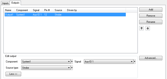
Your Matrox Iris GTR has 4 general purpose inputs (auxiliary input signals 3 through 6), and 3 general purpose outputs (auxiliary output signals 0 through 2). The IOs page of the Platform Configuration dialog allows you to add, rename, and assign a purpose to the available signals. For more information, see the Procedure for using the I/O steps section in Chapter 40: IO steps. The corresponding wires on the cables and breakout board connectors are described in the Matrox Iris GTR with Design Assistant Installation and Technical Reference. This manual also includes specific information for connecting to proximity switches, PNP and NPN modules of PLCs, as well as safely connecting to relays and inductive loads.
Additional auxiliary
input signal settings
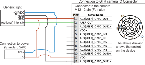
Connecting
auxiliary outputs to a generic light
The image below shows a wiring diagram using the M-12 I/0 and power connector to connect a generic light to the Iris GTR. For this example, the source type is set to strobe and the output signal will be on pin 12.
Additional auxiliary
output signal settings
Additional initial camera
settings
Your Matrox Iris GTR has the following additional settings that can be used to improve image acquisition.
Lighting
control from the camera
The Matrox Iris GTR I/O connector can provide:
-
A strobe signal, on auxiliary output signals 0, 1, or 2 (pins 10, 12, or 3, respectively) of the M-12 I/O and power connector.
-
A voltage controlled signal (dimmer/intensity control), on pin 2 (AREF_OUT) of the M-12 I/O and power connector; compatible with a lighting controller (such as, an Advanced Illumination inline control system (ICS3), a Smart Vision Lights Brick Spot Light, or a similar device).
For more information on Matrox Iris GTR multi-purpose auxiliary output signals, see the Communication with Matrox Iris GTR section later in this chapter.
To send a control signal to a lighting device, perform the following:
-
Enable the Strobe setting on the Cameras page of the Platform Configuration dialog.
-
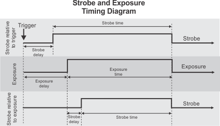
Specify the Delay and Time settings. The Time setting is typically set to the entire exposure. The Delay setting is relative to either the exposure or the trigger. Note that the trigger can be a software trigger, a periodic trigger, or an input signal, as specified in the Cameras page, under the Trigger section. To link the lighting information to either the exposure or trigger, use the Relative To setting, and as illustrated in the following timing diagram.
-
Specify the polarity of the auxiliary output signal to be sent to the light, with the Mode input setting.
-
Specify the Intensity setting to control the brightness of the connected illumination device. The Intensity setting can be set to any value between 0 - 255 which maps to 0 - 10V.
Camera focus
When focusing manually, adjust the image using the focus and aperture controls on the lens of your camera. If, however, you have a supported liquid lens, you can use the CameraFocus step to adjust the focus of the camera. You can either have the step automatically calculate the best focus position, either based on the algorithm selected on the Configuration pane, or you can explicitly specify the value of the lens' focus position. Refer to the Matrox Iris GTR readme for a list of supported liquid lenses.
For a Matrox Iris GTR with a supported liquid lens, valid focus positions are between 0 and 1023. Higher numbers will bring the focus point closer to the lens.
The current focus position is reported by the CurrentFocusPosition output. If the lens position is saved at the end of the CameraFocus step, the lens position is automatically re-established when the camera is allocated during subsequent project deployments. Otherwise, before the CameraFocus step is run, the focus position is the initial position of the lens.
When starting a project, it might be a good idea to set the focus position of the lens to the last returned optimal position, and then use a second CameraFocus step (set to Refocus) to confirm the setting.
The CameraFocus step uses one of the following strategies to find the best focus between the minimum and maximum lens position:
-
Auto focus. Automatically adjusts the lens to achieve the best focus possible. This is only possible with a supported liquid lens. Auto focus takes a range of positional values, and using the specified search strategy, determines the camera's best focus position. Auto focus is very useful if you don't know the focus position required for your image and provides a fast search for the best camera focus.
Note that, when performing an automatic focus operation, the images should not be saturated. Saturation can create strong artificial edges that move when the focus changes.
This method has 4 search strategies:
-
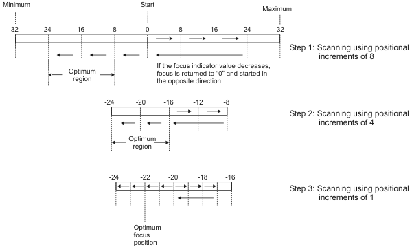
SmartScan. The smart-scan strategy performs 3 refocus searches, each with a smaller positional increment. You specify the initial positional increment; the subsequent increments are factors of the initial one. The default number of positions used to verify a peak is 2 but can be changed.
-
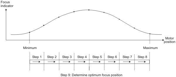
ScanAll. The scan-all strategy scans each position between the minimum and maximum and returns the position that produced the highest focus indicator.
-
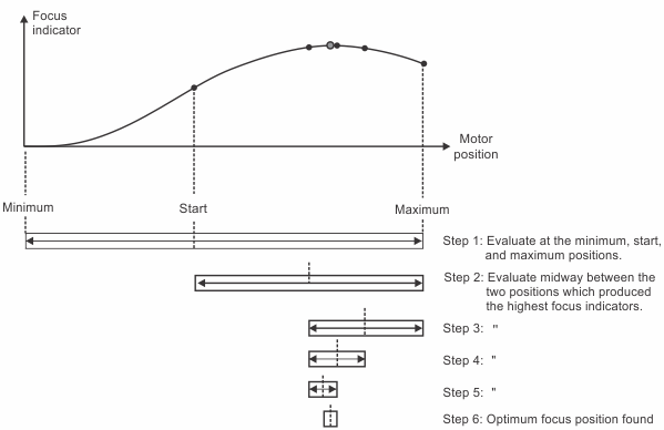
Bisection. The bisection search strategy breaks down the given positional range (start position to maximum position) in successive halves, step-by-step, until it finds the optimum focus position.
-
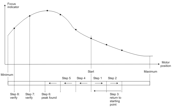
Refocus. The refocus strategy scans upward or downward until it finds the optimum focus position or until it reaches the minimum or maximum position. While scanning in one direction, if the focus indicator decreases continuously (indicating an out-of-focus condition), the focus position is returned to its starting point and scanning is started in the opposite direction. By default, if a peak in focus indicator values is found, the next 2 positions are scanned to make sure the peak is truly the optimum. If necessary, you can change the number of positions used to verify a peak.
-
-
Manual focus. Specify a set focus position for the lens. This is only possible with a supported liquid lens. The method takes the Focus value that you entered and sets the lens to that focus position.
-
Evaluate focus. Evaluates the focus level of a given image or an image grabbed with the current camera lens position and returns a focus indicator value. The higher the focus indicator value the better the focus. The value is image dependent.