Building the flowchart
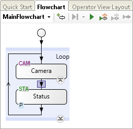
This section discusses the basics of building a flowchart, which involves adding and configuring steps. When you start a new project, you will be in the Flowchart tab, and you will see the default flowchart, which has a Camera step and a Status step within a loop.
For a full list of steps that can be added and their categories, see the Matrox Design Assistant steps and flowchart features section in Chapter 1: Introduction.
 General
procedure
General
procedure
To add and configure a step, perform the following:
-
Double-click on an arrow symbol in the flowchart (the step will be added below the arrow). The Add Step dialog opens. You can also open this dialog by clicking the Add step (
 )
toolbar button from the
Project toolbar, or click on the Add Step... context menu
item in the
Flowchart Step context menu.
)
toolbar button from the
Project toolbar, or click on the Add Step... context menu
item in the
Flowchart Step context menu.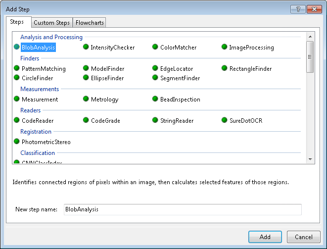
-
Click on one of the following pages in the Add Step dialog:
-
Steps page (selected by default). Allows you to select the step to add. Changing the name in the New step name text box changes the displayed name of the step in the flowchart.
A green dot next to the name indicates that the step has a permanent license, a yellow dot indicates that the step has a provisional license (click on the step to see when the provisional licenses expire), and a red dot indicates that the step does not have a license (and cannot be added to the flowchart). A multicolored dot (green/yellow or green/red) indicates that the operations of the step have different licenses, so some operations might not be available in the step with your current license.
-
Custom Steps page. Allows you to select a custom step to add. Several custom steps are provided; some are for demonstration and training purposes (such as the DateTime custom step), and some are for real applications (such as the OCR custom step).
-
Flowcharts page. Allows you to add a step that runs a previously saved subflowchart, or to create a new, empty subflowchart.
-
-
Click on the Add button. The Add Step dialog closes and your step (or subflowchart) is positioned in the flowchart. The order in which steps occur determines the order in which they are run. Typically, projects include multiple steps within a flowchart loop.
-
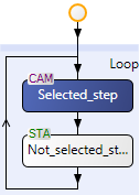
Select the step (or subflowchart) and configure it using the Configuration pane. You can use the Quick Access pane to help guide your configurations. Note that in the flowchart, the colors of the selected step (or subflowchart) are inverted.
While building the flowchart, you will typically want to run it and access its results. For more information on building your flowchart, see Part 3: Flowchart control, expressions, and variables.
Generally interacting with
flowcharts
Using the
Configuration pane
When you select a step, the Configuration pane displays the most important inputs that you can set. The Configuration pane also lets you configure an element in the Operator view layout tab.
In addition to inputs, the Configuration pane has the Navigation toolbar, which consists of:
-
Navigation buttons. Once you have displayed several inputs in the Configuration pane, you can use the Navigate backward (
 ) and
Navigate forward (
) and
Navigate forward ( ) toolbar buttons to cycle through them, even if
they relate to a different step. The selected step on the
Flowchart tab
will automatically change to match.
) toolbar buttons to cycle through them, even if
they relate to a different step. The selected step on the
Flowchart tab
will automatically change to match. -
Navigation links. When an input is displayed alone in the Configuration pane, the navigation options will display links to related inputs and a link to the default Configuration pane for the associated step. When the inputs displayed belong to a member of a collection (for example, a set of models), a dropdown list next to the name of the collection lets you move quickly to one of the other members.
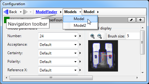
These inputs are also accessible in the Properties pane. Clicking on any of the inputs in this pane opens the Configuration pane with that input.
-
Simple, Link, and Advanced editor buttons. These buttons are on the top-right of the navigation options when you are editing an input. Clicking on these buttons opens an editor where you can specify a value for the selected input. Click the Simple button to specify an explicit value, click the Link button to specify a value that is a link to another input, and click the Advanced button to specify a value that is an expression. The following is an example of clicking the Simple button to specify an explicit value.
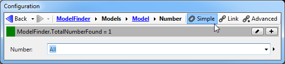
The editor buttons are only present when configuring a single input. When multiple inputs are displayed in the Configuration pane, you can access the Link and Advanced editors by clicking on the Alternate options button. For more information on using the simple, link, and advanced editors, see the Configuration pane and editors section in the Panes and editors reference chapter.
Using the Quick
Access pane
Flow control
steps
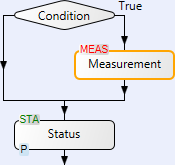
Matrox Design Assistant has several steps capable of altering the flowchart's flow. These steps can, for example, create loops, delay the flowchart's progression, and use a condition to create multiple paths, all depending on runtime events. For Flow Control steps, you enter an expression that evaluates when to execute a sequence of steps. The following example shows how to control the flow with a Condition step. If the condition is true (such as a model being found in an image), the Measurement step is run; otherwise, the flowchart runs directly to the Status step.
Flow Control steps are in the Flow Control section of the Add Step dialog; they include: Condition, Break, Switch, Continue, Halt, Loop, Status,and Error. For more information, see Chapter 23: Flow control steps.
Variables
Expressions
Expressions are statements that evaluate information and set or return a value. You can use expressions to set a step's input or a variable to a value, provide a Flow Control step with a conditional statement, calculate an output value of a step for a log file, or return a simple result. For example, to get the total number of occurrences found by the PatternMatching step, you can write the expression, PatternMatching.TotalNumberFound, in the Expression column of the Quick Evaluate pane; in the following case, the expression returns a value of 2.
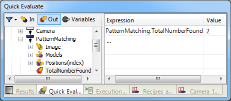
Although expressions can be explicitly written, you can create them interactively; this is the recommended way so that you can avoid syntax errors. You can typically create basic ones by accessing the related tree structure. In the above example, double-clicking on the TotalNumberFound output generates the expression.
Expressions range from simple to complex and can be composed of links to step inputs and outputs, functions, operators, and variables. You will typically specify expressions in the Configuration pane (to configure a step) and the Quick Evaluate pane (to retrieve a result). It is common to test and evaluate expressions (in the Quick Evaluate pane) before using them in their final destination (a step's Configuration pane). Note that you can drag and drop expressions across panes.
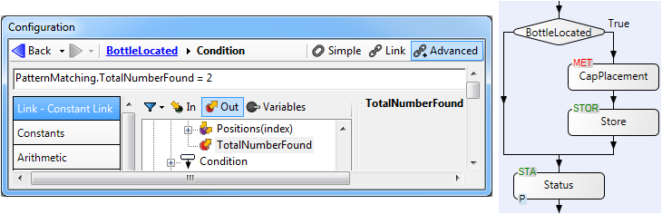
The following example shows an expression, from the Configuration pane of a Condition step that has been renamed BottleLocated. The expression uses a link to the TotalNumberFound output of the PatternMatching step to determine whether the required number of occurrences was found. Since this is part of a condition (BottleLocated), the subsequent steps are only executed if the expression is true.
If you need a complex expression, you will typically use the Configuration pane's Advanced editor. Complex expressions generally have multiple parts that often include functions, which return a value when given inputs (for example, the arithmetic function SQRT). There are many categories of functions, such as array-related functions; these can be useful when dealing with steps, such as the BlobAnalysis step, that have collections of inputs and outputs, which you must access using arrays. For example, the following expression uses 2 array functions, AVERAGE and SELECT, and a collection type output from the BlobAnalysis step. The following complex expression iterates through the collection of blobs found and returns their average area as a single number:
For more information about expressions, see Chapter 26: Building expressions.
Subflowcharts
Recipes
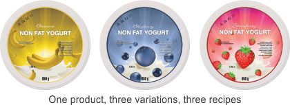
Recipes are a group of step inputs and variables used to inspect multiple variants in a family of related products. With recipes, you can manage product variations without duplication and without having to change what is common. The following is an example of a project that would use recipes (named Banana, Blueberry, and Strawberry) to inspect yogurt lids. Many aspects of this project would be common (for example, PLC communications, lid diameter, operator view publishing), while other aspects (handled by each recipe) would be different (for example, label color and status condition).
For more information about what recipes are and how to use them, see Recipes.