
Adding subflowcharts
If you add a subflowchart, it is essentially used as a step. This make it easier to reuse a flowchart structure across multiple projects. For example, you can have a subflowchart that handles communications with a PLC, which is often developed by someone other than the vision specialist. You can then add this subflowchart as a separate step to your main flowchart or to another subflowchart.
By adding subflowcharts, you can also simplify and organize more complex projects. Such projects should typically have one main, simple flowchart, that includes a series of subflowchart steps.
To add a subflowchart, access the Flowcharts page of the Add Step dialog.
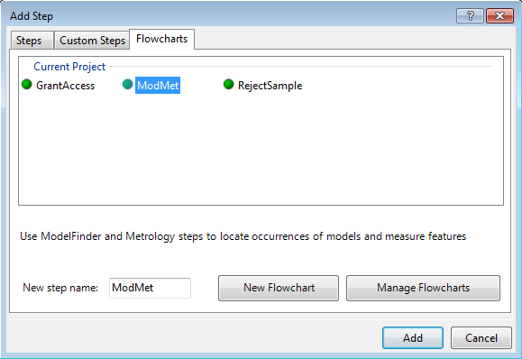
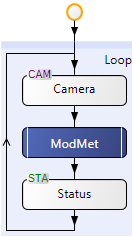
For a new subflowchart, enter a unique name, click the New Flowchart button, add a description, and click Add. Your project can now access the new subflowchart. By default, the subflowchart is added to the current (calling) flowchart. The subflowchart appears as a step, with double sidelines.
 Configuring a
subflowchart
Configuring a
subflowchart
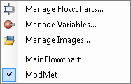
To configure a subflowchart, you must access it by double-clicking on the subflowchart step, or by selecting the subflowchart name with either the Flowchart menu item or by right-clicking inside the Flowchart view. A newly created subflowchart includes only the Start and End circle elements.

You can configure a subflowchart as you would a regular flowchart. For example, you can add new steps or copy steps from other flowcharts. To return to the calling flowchart, or to access any other flowchart in your project, use the Flowchart menu or right-click inside the Flowchart view.
A subflowchart's
inputs (parameters) and outputs
A subflowchart can have as many inputs (also referred to as parameters) and outputs as you require. At design-time, the Quick Evaluate pane displays the value of all inputs, outputs, and variables of all the flowcharts and subflowcharts in a project.
If you add a variable inside a subflowchart, set its Reset Point property to specify when the variable should be reset to its initial value. For more information, see the Lifetime section in Chapter 25: Variables and the Store step.