Procedure for using the ColorMatcher step
The following procedure provides a basic methodology for using the ColorMatcher step:
-
Run the project to the ColorMatcher step using an appropriate 3-band input image.
-
Specify the color-samples.
-
Specify the match regions.
-
Optionally, specify the main settings.
-
Optionally, specify the match settings.
-
View the output images and modify your settings until you are satisfied with the displayed results.
At any time you can change the active image for the ColorMatcher step to an available output image by using the dropdown list above the displayed image.
Based on your settings, the ColorMatcher step always tries to find the color-sample that is the best match for the match region.
To access results, you can use the Results pane, the Outputs tab of the Link editor, or the Quick Evaluate pane. For more information, see the Accessing ColorMatcher step results section later in this chapter.
To apply the same setting to multiple color-samples at once, use the Apply multiple dialog, accessible from the setting's Alternate options button.
Regardless of whether you are performing Color identification or Supervised color segmentation, the information in the procedures is applicable unless otherwise specified.
 Color-samples and match
regions
Color-samples and match
regions
To specify color-samples and match regions, perform the following:
-
For color-samples:
-
Click on the Add sample from region (
 ), Add sample from color
(
), Add sample from color
( ), or the Add sample from screen
(
), or the Add sample from screen
( ) toolbar buttons in the
Project toolbar. These buttons let you create color-samples
by defining them on the image, by selecting custom color values, or
by picking a color on the screen.
) toolbar buttons in the
Project toolbar. These buttons let you create color-samples
by defining them on the image, by selecting custom color values, or
by picking a color on the screen.The Samples area of the Configuration pane immediately displays the new color-sample and allows you to make modifications.
-
If a sample was created using the Add sample from region toolbar button (referring to a region in the image), you can mask out any part of the sample rectangle that is not the required color. To do this, select the sample and click on the Edit button. Select either Mask a rectangular part of a sample or Mask part of a sample using a brush.
It is preferable to set the brush color to a color noticeably different from the background color (black, for example). To do so, go to Change brush color.
-
If necessary, name the sample.
-
Repeat steps a to c for all samples.
You can check the result of the color matching by selecting Viewing color matches (in the Project toolbar).
-
-
For match regions:
-
Set the Match regions property in the Configuration pane to SpecificRegions, and click on the Define a region (
 ) toolbar button. See the
Search regions section in
Chapter 2: Building a project for more information on how to
define a shape.
) toolbar button. See the
Search regions section in
Chapter 2: Building a project for more information on how to
define a shape.For a single match region, select a shape from the Define a region toolbar button dropdown list to define a match region directly on the image.
For multiple match regions, select one of the Replicated... shapes in the Define a region toolbar button dropdown list. If the step specified in the Select a relative origin dropdown list in the toolbar provides multiple fixtures, there will be a match region oriented to each fixture.
-
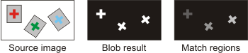
Use an image result from another step, such as the BlobAnalysis step or the ImageProcessing step, by selecting it from the Labeled image property in the Configuration pane. In this case, ensure that the Match regions property is set to LabeledImage. The non-zero pixel areas in the specified image represent the match regions. Note that disconnected areas with the same pixel value are considered as a single match region.
For example, it is useful to use the BlobAnalysis step to identify the blobs (non-zero pixels) that correspond to the match regions, then count the number of blobs of a certain color, say if you want to find out how many objects of a certain color are in the image.
Use the BlobAnalysis step results to define match regions as a labeled image output, then use the COUNT function with the ColorMatcher step results.
COUNT(FILTER(ColorMatcher.Regions("Region").Areas, Item.BestMatch.SampleName = Variables.PickColor))For more information on BlobAnalysis step or ImageProcessing step output images, see the Creation of an output image subsection of the Procedure for using the BlobAnalysis step section in Chapter 3: BlobAnalysis step, or the Morphology operations section in Chapter 9: ImageProcessing step, respectively.
-
The match region's position, dimension and angle can be modified interactively via the display image or through the Configuration pane.
When modifying the match region's parameters interactively via the display image:
-
To modify the match region's position, click and hold the edge of the match region and drag it to the expected location.
-
To modify the match region's dimension, click and hold the corners of the match regions (represented by red dots) and drag them to the expected location to resize. In the case of an elliptical or polygonal match region, this can be used to reshape the match region.
-
To rotate the match region, while holding the Ctrl key, click and hold the edge of the match region and move the cursor in a circular motion to rotate the region.
-
It is possible to create arc-shaped match regions using elliptical match regions. The region is defined using the 2 arc-modifiers and will correspond to the arc going from the outer arc-modifier in a clockwork motion to the inner arc-modifier.
When modifying the match region's parameters interactively via the Configuration pane:
Modify the match regions by clicking on the Edit match regions... button from the Configuration pane, accessing the Regions section, and selecting the region to edit. This is only valid when Match regions is set to SpecificRegions. To modify the match region, you can:
-
Change a region's position, dimensions or angle using an explicit value or by linking a value.
Linking a value can be useful if your match region is based on the found location of an object, such as occurrences in the ModelFinder step, or on the identified regions in an image, such as blobs in the BlobAnalysis step.
Make sure you are linking to the correct position and dimension values, even though settings between steps are not necessarily identical. For example, you can link the match region's X, Y, and Angle to the blob's CenterOfGravityXBinary, CenterOfGravityYBinary, and PrincipalAxisAngleBinary.
-
Note that for color segmentation, you will typically use the whole image as one match region. In this case, ensure that the Match regions property in the Configuration pane is set to WholeImage.
-
Main settings
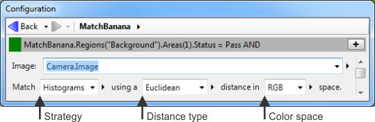
The main settings allow you to define the strategy, distance type, and color space of the match.
To specify the main settings, access the Configuration pane and perform the following:
-
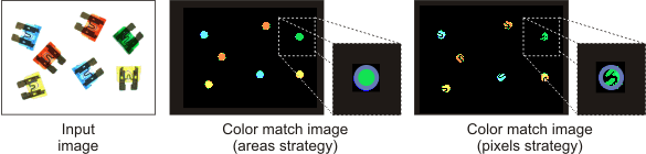
Specify the strategy with which to match a color by setting the Match property to Areas, Pixels, or Histograms.
-
For Areas, the match uses the average color of the color-sample and match region. This applies to color identification and typically yields the fastest results.
-
For Pixels, the match uses the average color of the color-sample and the color of each pixel in the match region. This can be used to determine the percentage of each color-sample in the target image.
-
For Histograms, the match uses the statistical color frequencies in the color-sample and the match region. This typically applies to color identification when dealing with a mixture of colors.
See the Match strategy subsection of the ColorMatcher step advanced concepts section later in this chapter for more information.
-
-
Specify the distance type with which to match a color.
The match is significantly based on the distance (difference) between the color of the color-sample and the color of the match region. The ColorMatcher step calculates this distance according to the distance type. A Euclidean distance type is a standard color distance that is typically sufficient, particularly for RGB or CIELAB. If you need to separate subtle color differences, you should use the Mahalanobis distance. For HSL, you should use a Manhattan distance.
See the Color distance subsection of the ColorMatcher step advanced concepts section later in this chapter for more information.
-
Specify the color space in which to match a color.
The ColorMatcher step interprets all input color data as RGB and, by default, performs the match in RGB, which is typically sufficient. However, the step can internally convert your RGB colors to HSL or CIELAB before the match by selecting them as the Space.
See the Color spaces subsection of the ColorMatcher step advanced concepts section later in this chapter for more information.
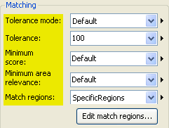
Match settings
The match settings allow you to define the tolerance, minimum score, minimum area relevance, and regions of the match.
To specify the match settings, access the Configuration pane and perform the following:
-
Specify the Tolerance mode and Tolerance.
The Tolerance mode specifies how to apply the Tolerance, which you can set to a specific value or Auto. For example, if you set the Tolerance mode to Absolute, the match applies the Tolerance value directly to the distance value. Relative and StdDev applies a Tolerance value which corresponds to the value specified multiplied by the distance between samples or a variation within a sample. The Tolerance is applied to all samples, but a sample can override it. This can be useful if you have multiple samples and only one requires a looser tolerance to match correctly. See the Color tolerance subsection of the ColorMatcher step advanced concepts section later in this chapter for more information.
These are the 2 most important settings and together, indicate the distance tolerance, which is the maximum color distance, between the color-sample and the match region, allowed for a successful match. The greater the tolerance, the greater the allowable distance (difference) between matching colors.
-
Specify the Minimum score for the color-sample.
Each possible match between a color-sample and a match region is given a color-sample score, in percent. In general, the closer the color distance, the higher the color-sample score. For a match, the color-sample score must be greater than or equal to the Minimum score.
You will generally not need to change the Minimum score, unless you are having a lot of difficulty identifying the best color-sample to match. See the Match score and area relevance score subsection of the Accessing ColorMatcher step results section later in this chapter for more information.
-
Specify the Minimum area relevance for the match region.
Each possible match between a color-sample and a match region is given a match region relevance score, in percent. This represents how certain you can be that the best-matched color-sample actually is the best possible match. For example, a high Minimum area relevance requires that the best-matched color-sample must be vastly superior to all other color-samples, while a low Minimum area relevance requires that the best-matched color-sample must only be marginally superior to the other color-samples.
You will generally not need to change the Minimum area relevance, unless you are having a lot of difficulty identifying the best color-sample to match. See the Match score and area relevance score subsection of the Accessing ColorMatcher step results section later in this chapter for more information.
-
Specify the Match regions, as previously discussed in the Color-samples and match regions subsection of this section.
Output images
The ColorMatcher step provides numerous results as output images which you can view by clicking on the Viewing... button. This button displays the name of the image you are currently displaying. Initially, this is typically the input image.
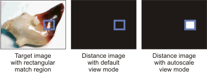
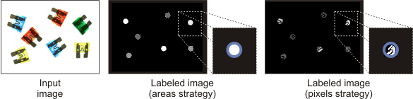
Note that output images can be significantly different depending on your match settings. For example, when setting the Match strategy property to Areas, output image results are drawn according to the general (mean) color of the match region, while for a Pixels strategy, results are drawn on a pixel-by-pixel basis.
To display an output image, click on the Viewing... button and select:
-
View color matches over input image. In this case, the ColorMatcher step displays the input image and, for each match region, the color of the best matched color-sample. Unmatched regions (or pixels) are filled with the outlier color.
-
View labeled matches. In this case, the ColorMatcher step displays, for each match region, the label (grayscale value) of the best matched color-sample. By default, sample labels start at 1 and are incremented by 1. They can, however, be specified.
-
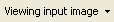
View distance image. In this case, the ColorMatcher step displays, for each match region, the distance (grayscale value) of the best matched color-sample. If the distance image does not display properly (for example, displays only black or very dark match regions), right-click on the image and select the Autoscale option from the View mode menu item. See the Displaying images with more than 8-bits section in the Display view reference chapter for more information.

-
View color matches. In this case, the ColorMatcher step displays, for each match region, the color of the best matched color-sample. Note that View color matches is the same as View color matches over input image, except the input image is not shown, instead, the portion of the image that is not part of any match region is filled with the Background color.