
Procedure for using the Measurement step
The following procedure provides a basic methodology for using the Measurement step:
-
Optionally, specify the number of marker occurrences.
-
Optionally, specify the marker characteristics, such as polarity, fit, width of stripe, and filtering.
-
Optionally, specify the sub-regions.
-
Optionally, specify the angular search settings.
-
Optionally, rename the marker.
-
Run the project to the Measurement step to update results.
-
Repeat these steps for each additional marker.
To access results, you can use the Outputs tab of the Link editor, the Results, or the Quick Evaluate panes. For more information, see the Accessing Measurement step results section later in this chapter.
 Define the
markers
Define the
markers
A Marker is represented by its search region on the display, but is composed of a number of image characteristics and a defined shape. Each marker has its own criteria for determining what is a valid edge, stripe, or circle. All optional settings have a default value that can be changed at any time, using the Configuration pane. To define the markers, perform the following:
-
Run the project to the Measurement step. This ensures all fixture providers are up to date.
-
Click on the Add edge marker (
 ), the Add stripe marker
(
), the Add stripe marker
( ), the Add circle marker
(
), the Add circle marker
( ), or the Add point marker
(
), or the Add point marker
( ) toolbar buttons in the
Project toolbar.
) toolbar buttons in the
Project toolbar. -
Fixture the marker using the pop-up dialog. You can select a fxture from a list, or by clicking on it in the image. For more information on fixturing, refer to Chapter 32: Fixturing.
-
Create a search region interactively on the display window.
-
For edge and stripe markers, a search region is a box, and for circle markers, a search region is a ring. For more information on how to create and configure a search region interactively in the display window, see the Search regions section in Chapter 2: Building a project.
-
For a point marker, set the location at which to add the point by clicking on the image. You can click and drag to set the angle and spacing to use when defining multiple points. For more information, see the Number of marker occurrences subsection of this section. Unlike edge and stripe markers, points are not found, they are defined at the specified position.
-
To cancel creating the region, press the Escape key at any time while drawing.
-
-
Optionally, configure a search region. There are 2 methods.
-
Use the display window to directly manipulate the search region using mouse click and drag.
-
Use the Configuration pane to enter the values of positional information. You can tweak the search region's location by specifying its center's coordinates (CenterX and CenterY), size (Height and Width), and Angle (search direction), in the Configuration pane's Search region... button. You can also enter variables, step results, or expressions to specify the search region's positional information. However, doing so will disable the ability to directly manipulate the search region in the display window.
Note that the edges of edge/stripe markers should enter and leave the opposite sides of the search region, except when using sub-regions (for more information, see the subsection below). The more precise the search region, the more likely the marker will be distinguished from other similar aspects (edges) of the image.
-
Repeat these steps to add more than one marker. You can also add markers by clicking on one of the Add buttons in the Configuration pane. To remove a defined marker, select it in the Markers tab of the Configuration pane, and click on the Delete button.
If you have defined several markers in one step, the selected marker will be highlighted on display. This is useful to help you identify the markers. However, in some cases it can slightly obscure annotations, such as the edge profile.
Number of
marker occurrences
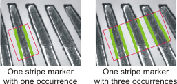
By default, the number of occurrences of a marker is one; that is, one search region, one occurrence of a marker. However, you can increase the number of marker occurrences to find in a search region. For example, one stripe marker can actually contain multiple stripe occurrences, found in the search region.
To change the number of marker occurrences, perform the following from the Configuration pane. Note that, unless otherwise specified, these steps apply to edges, stripes, and points. There can only be one circle marker in a search region.
-
Set the marker's Number. This value represents the number of occurrences.
For edge and stripe markers, Number can also be set to All, which will find all possible markers within the search region. This should only be done if the exact number of edges or stripes that should be found is unknown, and the image has very high contrast. Since point markers are defined (not found), you must specify an exact number.
-
For edge and stripe markers, set the marker's Minimum number. This value represents the minimum number of edges or stripes to locate in the search region.
Unless a minimum number is set, no results will be returned if the number of edges or stripes found falls below the Number input.
-
You can also specify a minimum and maximum spacing between the occurrences.
-
For point markers, set the Angle along which to place the points, and the Spacing to separate them.
Marker
characteristics
Marker characteristics are set to default values, which you can change at any time. Such changes can affect the search algorithm and its calculation of edges. Changing the default is typically done when the expected edge or stripe markers are not found. A setting with the value Any is ignored when finding the marker in an image.
The most important criteria for edge or stripe (caliper) location and measurement are found on the first Configuration pane. Properties such as, polarity, fit type, and number are most commonly adjusted. Other settings, such as filter and inclusion, are occasionally used to accommodate difficult images.
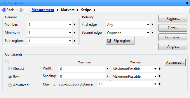
To change the default characteristics, perform one or more of the following from the Markers tab of the Configuration pane. Note that the following list applies to edge, stripe, and circle markers, unless otherwise specified.
-
Adjust the Region. The search region can be adjusted using specific values, but it is easiest to draw (or redraw) it in the image.
-
Set the Polarity. Use this to specify whether the edge to find should be positive (from dark pixels to bright pixels) or negative (from bright pixels to dark pixels), according to the search direction.
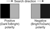
If you set the polarity to Any (default), the edge within the search region that has the sharpest contrast will be found. Since stripes have 2 edges, you can set the polarity for each of them. The polarity of the second edge can also be set relative to the first edge (Same or Opposite).
-
For circle markers only, set the Accuracy. To maximize the chance of finding a circle marker, especially in a difficult image, set this value to High. To decrease processing time for clean images with a single clear circle marker to find, set this value to Low.
-
Set the Constraints.
-
Set the Fit. For all markers, select Best for the strongest edge. For stripe and edge markers, select Closest for the edge closest to the beginning of the search region. For a circle marker, select Smallest or Largest for the smallest or largest circle in the search sub-region, respectively.
For all markers, the Advanced options allow changing the weighting or relative importance of every aspect of the determination of what makes an edge, though are rarely needed. For more information, see the Measurement step advanced constraints section later in this chapter.
-
Set the Width. For a stripe marker you can specify a minimum and maximum width for a valid marker.
-
Set the Spacing. For a marker with multiple edges or stripes, you can set a minimum and maximum space between the edges or stripes for a valid marker.
-
Set the Maximum sub-position distance. The overall position of an edge is determined from a projection operation which minimizes the effect of any bright or dark spots. However the angle of the edge is determined using small sub-boxes which can be skewed by bright shiny spots or dark spots. If the position of the edge is correct, but the line is tilted, the Maximum sub position distance can limit how far from the edge the search will be done. The default value is 10. For more information, see the Edge and stripe marker sub-regions subsection of this section.
-
Set the Minimum radius and Minimum radius to determine the smallest and largest circle marker allowable. This can be important when there might be multiple circles with the same center point, but with different sizes (radius lengths).
-
-
Set the Filter settings:
-
Filter type specifies the type of first derivative filter the search algorithm applies to perform the edge extraction within the search region. Typically, you do not need to change the default filter.
-
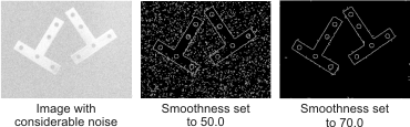
Smoothness specifies the degree of noise reduction to apply to the internal projection of the search region during the edge extraction. A setting of 0.0 indicates almost no noise reduction effect, while a setting of 100.0 indicates a very strong noise reduction effect. The default is 50.0. Note that Smoothness is only available if the Filter type is set to Shen (default).
-
Edge threshold specifies the edge value beneath which a grayscale variation, within the search region, is not considered an edge. To consider all grayscale variations as edges, irrespective of their values, set Edge threshold to 0.0. However, due to the increased number of edges, the measurement operation might take more time.
You can use the edge graph tool, accessible using the View edge values (
 )
toolbar button in the
Project toolbar, to determine the threshold value to
use.
)
toolbar button in the
Project toolbar, to determine the threshold value to
use.
For more information on filter settings, see the Search algorithm subsection of the Measurement step advanced concepts section later in this chapter.
-
-
Set the Inclusion point. When searching for a single stripe, you can specify an Inclusion point that must be either inside or outside of the required stripe.
Circle marker
sub-regions
Circle marker's use sub-regions differently from edge or stripe markers. All circle marker search regions are divided into sub-regions to find the circle marker, but typically there is no need to change the sub-region default parameters. If you need greater precision in finding your circle markers, for example, when locating one of 2 circles that are nearby or dealing with a particularly noisy or occluded image, you could configure the sub-regions. There are 2 parameters that affect circle marker sub-regions, number and chord angle. The Number property specifies the number of sub-regions, and the Chord angle property specifies the size of the sub-region based on the length of the chord resulting from the angle.
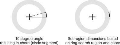
In general, more subregions and a smaller chord angle results in a more precise fit of the circle, while too many subregions and too small an angle can result in false positives and longer processing times. By default, there are 8 sub-regions, each with a chord angle of 10.
Edge and
stripe marker sub-regions
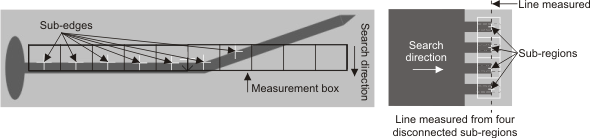
If required, you can divide the search region for edge and stripe markers into sections and have the Measurement step process sub-regions of these sections. That is, each sub-region acts like an independent measurement box; subsequently, only sub-regions are searched for markers. By default, sub-regions occupy the same area as their section, but can be reduced in size. To be found, the edge within the sub-region (sub-edge) must be continuous and must enter and exit the entire sub-region (rather than the entire search region) in the direction perpendicular to the search.
To fit a line to the edge, the algorithm uses all the sub-region positions. Sometimes a very bright reflection or other object falls in a sub-region box and gives a strong transition, but you don't want to include it in the line fit if it is actually an outlier. The sub-position distance limits the fit to transitions that are fairly close to the best fit.
Sub-regions allow you to make more complex measurements, such as finding the line equation for a discontinuous edge that is disconnected at regular intervals.
To divide a marker's search region into sub-regions, click on the Angle button from the Markers tab in the Configuration pane, and perform one or more of the following. Note that these steps apply to edge and stripe markers.
-
Set the Number. Use this to specify the number of sub-regions to use to locate a marker.
-
Set the Offset. Use this to specify the offset position of the sub-regions as a percentage of the distance from the center point of the sub-regions to the maximum possible offset (100%) in each sub-region.
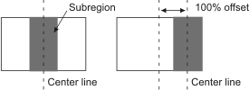
The direction of the offset (X or Y) is the same as the search direction, with positive values shifting the sub-region down or to the right, and negative values shifting the sub-region up or to the left. Sub-regions are offset as a group.
-
Set the Size. Use this to specify the sub-regions's box size as a percentage of their maximum possible size.
Sub-regions are always rectangular and extend from one edge of the search region to the other in the direction of the search. If Size is set to 100, sub-regions will be evenly distributed within the search region, with no space between them. If set to a smaller value, the sub-regions become thinner and occupy the specified percentage. Sub-regions will remain centered unless moved with their Offset property. Sub-regions are sized as a group.