Measurement step overview
 Previous
- Next

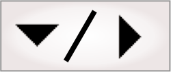
The Measurement step allows you to find occurrences of specified markers in an image. It can find an edge, stripe (pairs of edges or calipers), and/or circle marker. Occurrences of a marker are found, within the marker's search region, based on differences in pixel intensities. One Measurement step can search for any number and any combination of edge, stripe, or circle markers.
The search region of a marker is specific to the type of shape (edges, stripes, and circles). It defines the area in which to search for occurrences of the marker and the direction in which to perform the search. On the display, a marker is represented by its search region. Criteria that you can set for the marker include the polarity of the edge(s), whether the fit is based on edge strength (best) or location closest to the start of the region, how many sequential occurrences are within one region, and their spacing if multiple are expected. The Measurement step can search for a collection of markers, each with their own search regions and characteristics.
Upon finding the occurrence(s) of a marker, the Measurement step returns, for each occurrence, its position and feature measurements (such as its width and angle). Also, when searching for a number of occurrences of the same marker in a search region, you can retrieve the spacing between these occurrences. Statistics of multiple occurrences are returned as well, including minimum, maximum, mean, and standard deviation. During design-time, you can access these measurements most easily from the Quick Watch flyout panel, and the statistics from the Results pane; for other options available to review the results, see the Accessing Measurement step results section later in this chapter.
Calculations in the Measurement step are made with subpixel accuracy and results are returned in real-world units if the image is calibrated (for more information, refer to the Calibration section in Chapter 30: Calibration). You can use 8-bit or 16-bit unsigned grayscale images.
The Measurement step also allows you to define point markers, which are a special type of marker. Unlike edge, stripe, and circle markers, point markers are not found; they are placed manually at the required location. Point markers are generally used as a reference for marking expected positions, and are particularly useful for marking where an occurrence is missing. The position of point markers can be linked to the results of another step, such as a previous pattern matching or blob analysis operation.
Note that, to find one edge marker in a single search region, you can also use the EdgeLocator step. The EdgeLocator step uses the same underlying MIL functions as the Measurement step; however, the EdgeLocator step offers fewer inputs. The EdgeLocator step is useful for cases with clear edges and simple circumstances, and if searching for a single edge occurrence.
 Typical uses of the
Measurement step
Typical uses of the
Measurement step
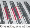
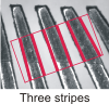
The Measurement step is very useful and can be used for a wide range of analysis. For example, you can measure the width of a pin (stripe marker) on a connector, or measure the spacing between multiple pins (stripes). In the following example, you could verify if a series of 3 leads on a lead frame are of equal width or if the spacing between them is within specifications, by searching for multiple occurrences of a stripe marker and using the statistics results of that marker.
The Measurement step results can also be used to build a fixture directly. Each measurement marker occurrence provides a fixture output with position and orientation information for further steps. The angle of the fixture will vary depending on the search box orientation.
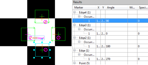
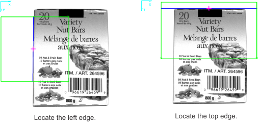
You can also build a fixture using the results of a Measurement step with the Fixture step. For example, you can use 2 edge markers to determine the 2 edges of a corner and then have a Fixture step, set to TwoLines definition mode, define a fixture, located at the point of intersection between 2 extended edge results. In the following images, the top and left edges are determined using edge markers found with the Measurement step; a Fixture step is then used to define a fixture at the top-left corner.
For more ways to fixture using the Measurement step, see the When to use the Fixture step subsection of the Fixturing in an analysis step section in Chapter 32: Fixturing.