Fixturing in an analysis step
Fixtures can be created using a Fixture step, or by most steps that produce position and angle results (all but the Metrology step). How to use a fixture in a step varies from step to step, but usually relies on fixturing one or more search region. Some common situations of fixture creation and fixture use in analysis steps include: using a single model occurrence as a fixture, using edges or blobs to create a fixture, and looping through multiple model occurrences creating a fixture from each.
 Using a single model
occurrence as a fixture
Using a single model
occurrence as a fixture
A common case where fixturing is used is that in which you use a ModelFinder step or a PatternMatching step to identify a single part in an image, and use that step's results as a fixture for future steps. The Measurement example, accessible from the Quick Start tab, demonstrates a typical case of a single model occurrence that provides a fixture.
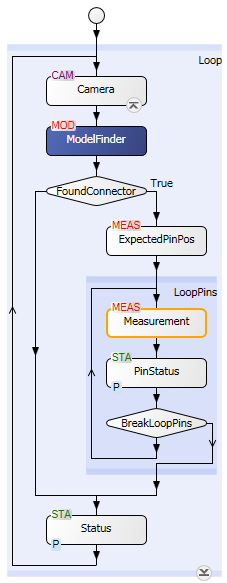
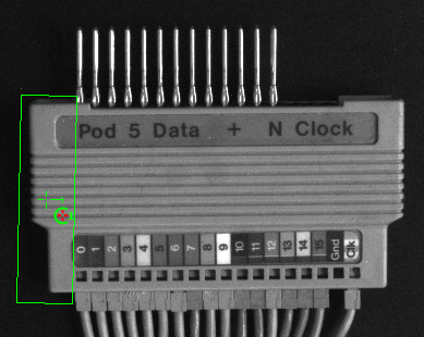
In this example, the ModelFinder step finds a single model occurrence (that is, the side of the part) that can be used as a fixture; the example then uses that reference to inspect the pins on top of the part.
When selecting a fixture from the results of a previous step, for the search region of a subsequent step (such as the Measurement step), you will see a list similar to the following.
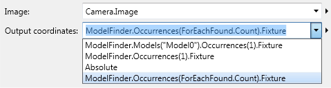
Note that Occurrences(1) means to use the position and angle of the first occurrence as a fixture. If there are multiple occurrences, the list of available fixtures will present the occurrences both in order of score and grouped by model. See the Using different fixtures from multiple occurrences subsection of this section.
Note that to avoid runtime errors, it is essential to link to results that are valid. A Condition step should always be used to check that the fixture provider was successful in finding the object before running steps that use the resulting fixture.
Using blobs
or edges as fixtures
The results of BlobAnalysis steps, EdgeLocator steps, or Measurement steps are commonly used as fixtures for future analysis steps.
If the part can only shift in one direction, it might be sufficient to simply locate one edge for fixturing. The CroissantInspection example, accessible from the Quick Start tab, is a typical case of an object being located using the BlobAnalysis step and used as a fixture in this way.
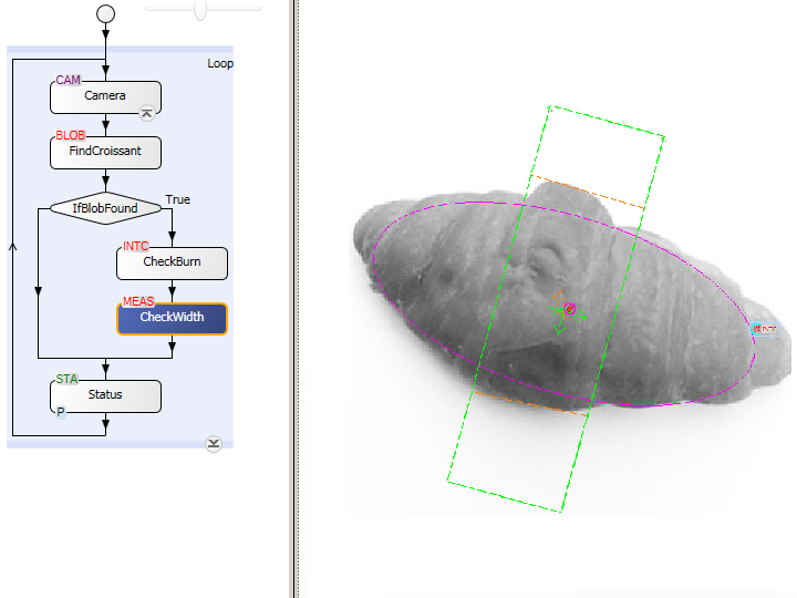
The BlobAnalysis step is often used to count or locate objects anywhere in the image, especially when they have irregular shapes that do not lend themselves to being analyzed by the ModelFinder step or PatternMatching step. The BlobAnalysis step is a fast and simple way to locate an object that is easily separated from the background. In the above example, the blob results are used to fixture the subsequent steps that check for burns and measure the width of the croissant. It is recommended that you use blob filters and, optionally, blob sorting so that the blob occurrence used for the fixture is unambiguous (for example, always the largest blob).
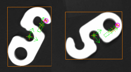
The fixture output of a BlobAnalysis step is based on the principal axis and center of gravity features. The angle of the fixture will always fall in the range of 0-90 degrees and 270-360 degrees. Consequently, fixtured regions will always appear on the same side of the center of gravity, which is not suitable for non-symmetric objects. The image above is an example of when the fixture from a BlobAnalysis step would not be used.
Using different
fixtures from multiple occurrences
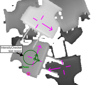
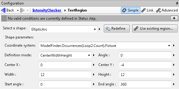
The following shows an example of using different fixtures from multiple occurrences of a model. The IntensityChecker step is placed in a loop such that successive model occurrences are examined. To accomplish this, the occurrence index is linked to the loop count, as in: ModelFinder.Occurrences(Loop2.Count).Fixture. At each iteration, the occurrence's fixture output is set as the coordinate system for the IntensityChecker step's test region.
When to use
the Fixture step
Typically, you would directly select a fixturing output of a previous analysis step to fixture a current step. However, there are cases where you want to construct a fixture from multiple results. In this case, you need to use a Fixture step. The Fixture step can create fixtures from the intersections of 2 lines (corner), from a point and an angle, and between 2 points. For example, you can use a Fixture step to create a fixture based on the occurrence position of 2 different edge markers.
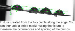
In the example below, we use the fixture step to create a fixture between 2 points for an object that can appear within a range of angles. 2 narrow, widely-spaced search boxes are placed on points in the image, and the measurement results of these boxes can be used by the Fixture step to create the fixture. This method is less time consuming and more efficient than finding the angle from a single large search region with angle mode enabled. For more information on angle mode, see the Angular search settings subsection of the Procedure for using the Measurement step section in Chapter 7: Measurement step.
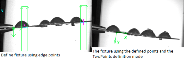
Once the Fixture step defines the fixture, it can be used by following steps. In the following image, a stripe marker is placed in the image using the fixture, allowing the verification, measurement, and counting of the number and spacing of bumps on a metal plate.