Fixturing overview
 Previous
- Next

Some production methods use mechanical fixtures or robots to present a part to be inspected. In those cases, the vision system always sees the part in the same position and orientation. However, in many cases, the objects are not physically fixtured and move in the field of view; in these cases, Matrox Design Assistant allows you to fixture the objects in software.
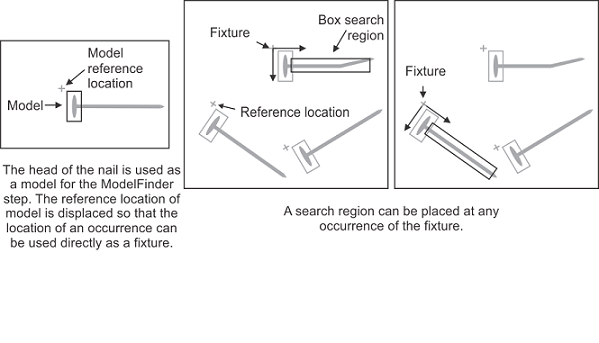
Fixtures are coordinate systems in which regions, positions, and templates are defined, and relative to which results can be returned. A fixture consists of an origin point and an angle, and can be defined based upon some previous analysis that locates the object. Fixture outputs are produced by most steps that produce position and angle results (for example, the ModelFinder step or the PatternMatching step). Fixtures can also be created from a combination of results, such as the intersection of 2 line results, removed using the Fixture step.
If you specify the Analysis and Processing of an object relative to a fixture, you won't need to re-adjust these settings for each instance of the object, since each instance will have a fixture at the same relative location. This means that you can avoid transforming results obtained from different instances of an object for comparison purposes.
In Matrox Design Assistant, all search regions have a Coordinate System input that takes fixture values. Fixtures can be selected directly from the dialog that appears when creating objects such as search regions. The list includes result occurrences of the analysis steps, or they can be constructed from positions, angles and line intersections using the Fixture step. Fixtures are re-evaluated every time the results on which they are based change value; the fixture will re-orient itself accordingly.