Procedure for using the Metrology step
The following procedure provides a basic methodology for using the Metrology step:
-
Add features, keeping in mind a feature's reference frame.
The Metrology step's feature and tolerance settings are optional; adjust them to fine-tune the results.
You can use the Project toolbar to add features and tolerances, or to define a new local reference frame.
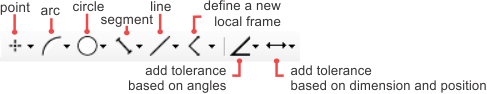
 Add features
A feature is a geometric primitive, such as a point or a segment. You can add 3 different types of features: constructed (built from other features), parametric (defined with explicit values), and physically measured (extracted from a search region in the image). Constructed features can be built from results of other steps and other constructed, parametric, and physically measured features.
Note that, for physically measured features, other analysis steps might more effectively extract the required shape. In situations where multiple shapes and edges are very close together or the required shape is not the most strongly contrasted, you can use the Measurement step, EdgeLocator step, BlobAnalysis step, or use a shape finder step (such as the RectangleFinder step, CircleFinder step, EllipseFinder step, or SegmentFinder step).
You can use the Project toolbar to add constructed or parametric features. Use the Configuration pane to add physically measured features. For more information on adding features, see the following:
-
For constructed features, see the Constructed features section later in this chapter.
-
For parametric features, see the Parametric features section later in this chapter.
-
For physically measured features, see the (Physically) measured features section later in this chapter.
Parametric and physically measured features are defined relative to a reference frame. See the Reference frames subsection of this section.
Add geometric
tolerances
A geometric tolerance sets the allowable variation of a length, angle or position of a feature, or the acceptable relationship between multiple features. For more information on geometric tolerances, see the Geometric tolerances section later in this chapter.
Reference
frames
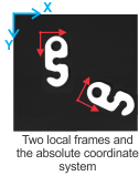
Every parametric and physically measured feature is defined relative to a coordinate system or fixture, known as a reference frame. If you reposition a reference frame, all features and feature search regions associated with that reference frame are altered accordingly.
To define a feature or search region, you can use one of the following:
-
The fixture output from another step. For example, if your parts move at runtime, specifying a model occurrence's fixture output as the reference frame ensures that associated features move along with the part.
-
The absolute coordinate system. The absolute coordinate system's origin (0,0) is aligned with the image's top-left corner, unless an applied calibration changes the origin. You cannot move the absolute coordinate system. Therefore, use it as a reference frame for features that remain in place from one image to the next.
-
A local frame. This is a fixture that only exists inside the Metrology step; it is a user-defined reference frame. If a suitable fixture does not exist, or if the absolute coordinate system does not meet your needs, add a local frame. You can set a local frame at an offset from another step's fixture output, which is useful if relocating the fixture output is not convenient or possible.
For more information, see the Reference frame section later in this chapter.
By default, position and angle results are returned with respect to the absolute coordinate system. If you need to retrieve metrology results in a coordinate system that is different from the absolute coordinate system, reposition the global reference frame.