Metrology step overview
 Previous
- Next

With the Metrology step, you can define features and geometric tolerances to measure and validate objects.
The Metrology step is an excellent geometry calculator that can perform geometric constructions, including finding an object's center and bisector, and establishing distance and angle relationships between features, including features created in other steps.
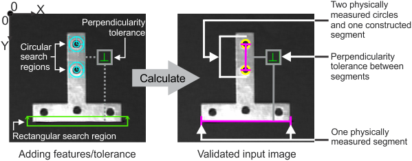
A feature is a geometric primitive, such as a point or a segment. You can add 3 different types of features: constructed (built from other features), parametric (defined with explicit values), or physically measured (extracted from a search region in the image). The Metrology step supports the following feature geometries: point, edgel, arc, circle, segment, line, and local frame. Note that not all feature geometries are available for each type of feature. For example, you can add a constructed or parametric line, but not a physically measured line. Also note that, unlike other features, a point or an edgel feature can contain multiple points or edgels, respectively.
You can apply tolerances to validate feature geometries. For example, you might want to verify a feature's length, or that 2 features are perpendicular. To do this, you can add a geometric tolerance, such as minimum distance or perpendicularity. The Metrology step also shows annotations from all other steps that produce points, edges, circles, and fixtures so that constructions and tolerances can use them directly (auto-import). Tolerances applied to the measured or constructed features provide status results.
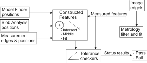
The following diagram illustrates the various source steps or measurements that you can use to build a constructed metrology feature. These include features from other steps (for example, the BlobAnalysis step or the Measurement step).
Every parametric and physically measured feature is defined relative to a coordinate system or fixture, known as a reference frame. A reference frame can be the fixture output from another step, the absolute coordinate system, or a local frame. A local frame is a fixture that only exists inside the Metrology step; it is a user-defined reference frame. If you reposition a reference frame, all of its associated features and feature search regions are altered accordingly.
The Metrology step provides complete support for calibration. If the image is calibrated, calculations are performed in calibrated real-world units such that, without physically correcting your images, measurements and calculations are correctly made even in the presence of distortion, and results calculated in real-world units.
Matrox Design Assistant comes with several metrology example projects. Use the examples as a starting point for writing your own applications. You can access examples from the Matrox Design Assistant Quick Start tab.