Parametric features
Parametric features are geometric primitives usually defined by drawing in the image. You can also define parametric features using explicit values in the Configuration pane. Explicit value inputs are useful when the parameters of the feature link to values from the PLC or a text reader, or when establishing a datum (for example, a reference line).
You can build the following features parametrically: point, arc, circle, segment, line, and local frame.
Parametric features do not have a search region, since these features do not actually exist in the image.
The following methodology shows how to add a parametric segment feature. Note that information on how to define each parametric feature is available at design-time, from the Quick Access pane or the Construction control panel.
-
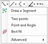
Click the Define segment toolbar button in the Project toolbar to reveal the dropdown menu.
-
Select Draw a Segment.
-
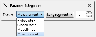
Choose the reference frame with which to associate the segment by selecting from the Fixture dropdown list in the Construction control panel. Note that you might need to further specify the exact reference frame in the Construction control panel. For example, to choose a fixture output of a Measurement step, select the specific marker and its occurrence number.
-
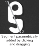
Draw the segment. Click on the location in the image that represents the segment's start point and drag to the end point. You can cancel the operation by pressing the Escape key before releasing the mouse. If necessary, redefine the segment from the Configuration pane, or interactively in the image.
 Adding a
parametric line
Adding a
parametric line
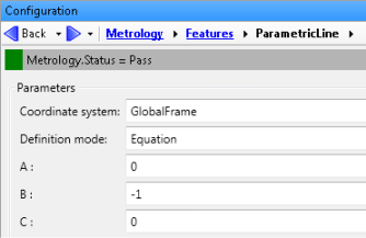
When adding a ParametricLine from the Configuration pane, you must choose a Definition Mode: either TwoPoints or Equation. The Equation mode has 3 parameters (A, B, and C), which refer to the line equation: Ax + By + C = 0.