Geometric tolerances
A geometric tolerance sets the allowable variation of a length, angle or position of a feature, or the acceptable relationship between multiple features.
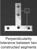
To add a tolerance, you must specify its type (such as length or perpendicularity), the range of acceptable results (that is, the tolerance's minimum and maximum values), and the features to which it is applied. For example, you can set the length tolerance of a segment to be between 90 and 100 pixels, or you can set the perpendicular tolerance between 2 segments to be between 89.95 and 90.05 degrees. Optionally, you can set warning thresholds to alert you when the resulting tolerance is close to, but outside of, a passing range.
The status of the geometric tolerance returns Pass or Warning if the tolerance meets the specified pass or warning requirements, and Fail if it does not, as illustrated below.
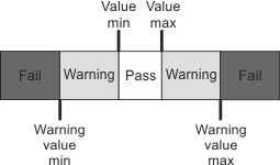
Note that the tightest range specifies values that Pass. A warning value is not considered a pass, so the warning ranges fall above or below the Pass range's Value max and Value min settings, respectively.
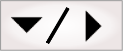
The following illustration lists the geometric tolerance types. Note that information on how to define each tolerance is available at design-time from the Quick Access pane or the Construction control panel.
|
Angle-based tolerances |
Dimension and position based tolerances |
|
|
Angularity |
DistanceMin/DistanceMax |
PositionX/PositionY |
|
Perpendicularity |
Length |
Straightness |
|
Parallelism |
Radius |
Roundness |
|
Concentricity |
||
 Using the
Project toolbar
Using the
Project toolbar
The following is a basic methodology for defining geometric tolerances using the Project toolbar:
-
Add a tolerance using the Add angle tolerance (
 ) or Add dimension/position
tolerance (
) or Add dimension/position
tolerance ( ) toolbar buttons.
 -
Select the Tolerance type from the dropdown menu (for example, DistanceMin).
The Construction control panel will then appear, giving contextual information as to which features are supported for the chosen tolerance type. For instance, the DistanceMin tolerance can be based on almost any 2 features, with the exception of lines.
-
Select the features on which to apply the tolerance (for example, a segment and a circle). To do so, in the image, click on a feature or its callout to add it to the list of Base features in the Construction control panel.
-
Click on the green checkmark in the Construction control panel to confirm the Base features. The tolerance is added. Note that the Configuration pane updates to display the tolerance options, where you can input specific tolerance values.
-
Specify the tolerance's minimum and maximum values.
For example, for a DistanceMin tolerance, you could set the minimum and maximum values to 90 and 100 pixels, respectively. If you do not specify warning values, the status of the features on which the minimum distance tolerance is applied will return a Pass if the distance is within this range; features with a distance below 90 or above 100 pixels will return a Fail.
-
Optionally, specify the tolerance's minimum and maximum warning values.
For example, set the minimum and maximum warning distance values to 85 and 105 pixels, respectively. Distances between a warning value and its respective minimum or maximum tolerance, set in step 5 above, will return a Warning status.
Using the
Configuration pane
Setting
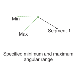
an angularity tolerance
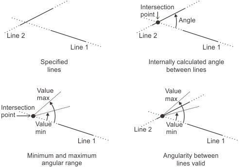
An angularity tolerance validates that the angle between 2 features falls within the specified angular range (for example, that 2 lines intersect at an angle between 25° and 35°). You can add an angularity tolerance between the following features: 2 lines, 2 points, 2 segments, or between a linear feature (segment or line) and an edgel feature. In addition, you can add an angularity tolerance for one segment.
-
2 line features.
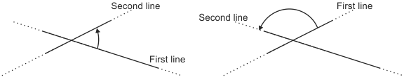
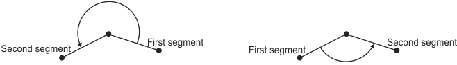
To validate the angularity between 2 line features, Matrox Design Assistant considers the angle between the lines to be, counter-clockwise, from the first line to the second line. The angularity status will fail unless the angle falls within the minimum and maximum pass values set for the tolerance. To designate the valid angular range, set the Value min and Value max tolerance limits as angles applied counter-clockwise from the first line to the second line, around the intersection point of the 2 lines.
The order in which you select the lines can affect your results. For example, the same line pair is measured differently, depending on which line is selected first.
-
2 point features.
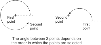
An angularity tolerance between 2 points is measured from the first to the second point, applied in a counter-clockwise direction. The start point for the angle is an imaginary axis originating from the first point, parallel to the X-axis of the point's reference frame.
-
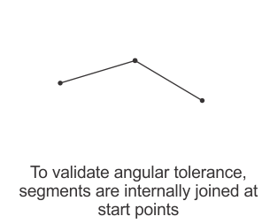
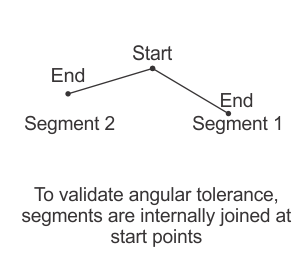
2 segment features.
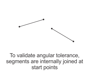
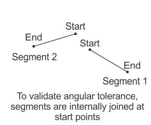
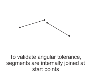
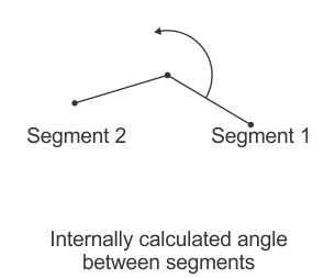
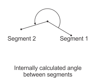
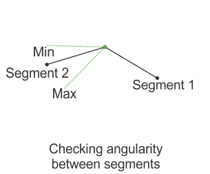
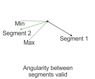
To validate the angularity between 2 segment features, Matrox Design Assistant internally connects each segment at their start point and considers the angle from the first to the second segment, applied in a counter-clockwise direction. The angularity status returns a Pass if the angle falls within the minimum and maximum pass values set for the tolerance. To designate the valid angular range, set the Value min and Value max tolerance limits as angles applied counter-clockwise around the start point of the first segment. Note that Matrox Design Assistant does not physically rearrange the specified segments, it only orients them internally to measure the required angles.
The following animation illustrates angularity between 2 segment features.
Each segment's start point, as well as the order in which you select the segments when adding the tolerance, can affect your results. For example, the same 2 segments are measured differently, depending on which segment is selected first.
To find which end of a segment is the start point, click on its callout, and note the listed StartPosition and EndPosition in the Quick Watch flyout panel. If necessary, click on the filter button at the top-right of the panel; then, choose the Advanced display mode to see these properties.
-
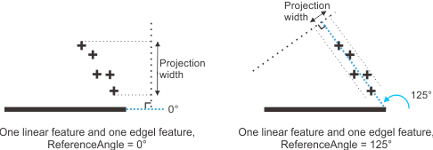
A linear feature (segment or line) and an edgel feature.
For one linear feature (segment or line) and one edgel feature, Matrox Design Assistant validates the edgel feature's width. The width is measured from a projection of the edgel feature onto an imaginary line that is perpendicular to the specified angle (ReferenceAngle). The angle is in the counter-clockwise direction relative to the linear feature. To designate the valid width range, set the Value min and Value max tolerance limits in the Configuration pane. Typically, you should set the minimum width value to 0. The width of the projection is in pixel or world units. Note that the second feature specified must be edgel.
Using
multiple geometric tolerances
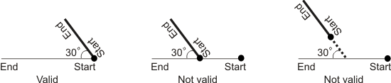
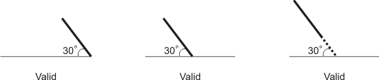
To accurately represent a relationship between features, you might have to validate the features with multiple geometric tolerances. For example, to verify the following result, you can set a 30° angularity tolerance between 2 segments.
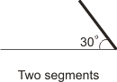
However, using only the angularity tolerance, each of the following results has a valid tolerance status.
In this case, you need to add an additional tolerance to check the location of the segments. To do so, add 2 constructed point features at the start of each segment. You can then add a distance tolerance for these 2 points, ensuring they are at the same location. To satisfy the required feature relationship, both the angularity status of the segments and the distance status of the points must be valid.