Constructed features
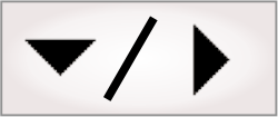
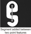
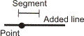
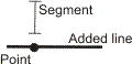
Constructed features are geometric primitives (such as points, arcs, circles, segments, lines) built from other step results and other features (such as constructed, parametric, and physically measured features). For example, you can add a constructed segment by building it from 2 constructed point features (as seen below), or by building it from the results of other steps, such as the BlobAnalysis step.
 Selecting base
features
Selecting base
features
Using the
Project toolbar and Construction control panel
The following is an example of adding a constructed segment feature. You can consider this a basic methodology for adding constructed features using the Project toolbar. Note that information on how to define each constructed feature is available at design-time, from the Quick Access pane or in the Construction control panel, which is a pop-up panel that appears when you select a construction method from the Project toolbar. For a summary of all available features and how to construct them, see the Feature construction in detail subsection of this section.
-
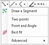
Click the Define segment toolbar button to reveal the dropdown menu.
-
Select Two points, Point and Angle, or Best fit (if working from multiple points or edgels) from the dropdown menu. Then, construct the segment as described below:
-
Two points. In the image, click on a point or its callout; then, click on a second point to define the segment.
-
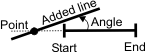
Point and Angle. Click on a point or its callout; then, enter the Angle and Length for the segment.
-
Best fit. Click on at least 2 points from which to define the best fit segment.
When you click on a point or its callout, the point is added to the list of Base features in the Construction control panel.
-
-
Click on the green checkmark in the Construction control panel to confirm construction of the new segment.
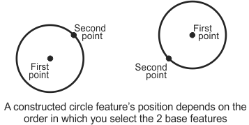
Note that, depending on the construction method, the specified order of the base features can change how the new feature is built. For example, when constructing a circle using the basic construction method, the first base feature must be a point or edgel that represents the circle's center, and the second base feature must be a point or edgel that represents a position on the circle's circumference. To change the order of a base feature, select it in the Construction control panel and use the up/down arrows to move it in the list.
Note that you cannot add a constructed edgel feature using the Project toolbar. Use the Configuration pane instead. See the Using the Configuration pane subsection of this section.
Using
the Construction control panel
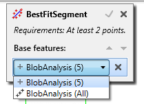
The Construction control panel will give contextual information regarding what kind of base features are required to build the requested feature; for instance, a best-fit constructed segment can only be built using 2 or more points or edgels.
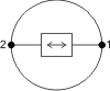
When creating a constructed feature and you click on a callout in the image, an item is added to the list of base features in the Construction control panel. Some base features are associated with multiple result values. For example, a BlobAnalysis step might produce position results for numerous blobs. In the case of multiple result values, clicking on the listed base feature in the Construction control panel and then on its associated dropdown list offers the indexed result and the All option. Select All to construct the feature using all related items. This is convenient when using a fit operation to build a constructed feature, such as a best fit, inner fit, or outer fit segment.
A similar example is when a ModelFinder step or PatternMatching step uses multiple models. You can access a specific, indexed occurrence or All occurrences of a model, or All occurrences of all models. This is convenient for fit operations. (For more information, see the Accessing PatternMatching step results section in Chapter 12: PatternMatching step).
You can rename a feature by clicking on its name at the top of the Construction control panel.
Using the
Configuration pane
Modifying base
features
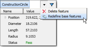
If you need to change one of the base features after the constructed feature has been created, select the constructed feature by clicking on its callout in the image or from the list in the Configuration pane. Click on the Redefine dropdown list item in the Quick Watch flyout panel or on the Redefine button in the Configuration pane to make the Construction control panel reappear.
Examples
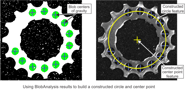
A typical example for a constructed feature is using the results from a previous BlobAnalysis step. In the image of the gear below, the required constructed features are one large circle and its center point. To build these features, the 12 smaller holes within the gear are identified using the BlobAnalysis step. These blobs' centers of gravity are then used in the Metrology step to create a best-fit constructed circle feature. Finally, the centre of that circle is added as another constructed feature.
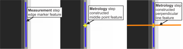
Another example of a constructed feature is a point at the middle of a measured segment. In this case, the Geometry of the new constructed feature is a point, the build operation (Construction method) is Middle, and the Base feature is MeasuredSegment. Once constructed, you can use the new point and the segment from which it was built as the base features for a constructed perpendicular line.
In the illustration below, an edge marker from a Measurement step is the base feature for the Metrology step's constructed point and constructed perpendicular line features.
Feature
construction in detail
You can construct the following features: point, edgel, arc, circle, segment, line, and local frame. Each feature is built from one or more base features using a build operation (summarized in the tables below). Note that there is also a clone build operation, but it is not discussed, since in each case, it simply recreates the feature you provide.
Constructed features
using fit operations
You can construct an arc, circle, or segment feature using a fit operation with base features that are points or edgels. The fit operations are the same as those used for measured features; for information, see the Best fit, inner fit, and outer fit operations subsection of the (Physically) measured features section later in this chapter.
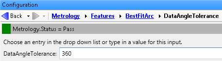
Note that, when constructing a best fit arc, circle, or segment, and using edgels as the base feature, the newly constructed feature might not appear in the display view. To ensure the feature's visibility, change its Data angle tolerance input to 360 degrees.
Base features of a
constructed arc feature
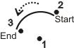
An arc is a continuous portion of a circle. You can construct arcs using 3 points, or with a best fit operation based on numerous points or edgels. The following table illustrates the build operations and required features to construct arcs:
|
Build operation (method) |
Base feature(s) used to build the arc |
||
|
3 points |
Numerous points or edgels |
||
|
Basic construction |
|
Not available |
|
|
Best fit |
|
|
|
Base features of a
constructed circle feature
A circle is a closed curve of points where each point is located at the same distance from one center point. You can construct circles using 2 points, or with a fit operation based on numerous points or edgels. The following table illustrates the build operations and required features to construct circles:
|
Build operation (method) |
Base feature(s) used to build the circle |
|
|
2 points |
Numerous points or edgels |
|
|
Basic construction |

|
Not available |
|
Best fit |
Not available |

|
|
Inner fit |
Not available |

|
|
Outer fit |
Not available |

|
Base features of a
constructed segment feature
A segment is a part of a geometric line that is defined by a start point and end point. You can construct segments using 2 points, or with a fit operation based on numerous points or edgels. The following table illustrates the build operations and required features to construct segments:
|
Build operation (method) |
Base feature(s) used to build the segment |
|
|
2 points |
Numerous points or edgels |
|
|
Basic construction |

|
Not available |
|
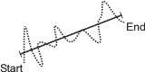
Best fit |
|
|
|
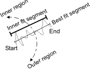
Inner fit |
|
|
|
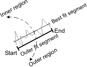
Outer fit |
|
|
Base features of a
constructed line feature
A line is a one-dimensional geometric primitive that is straight and infinitely long. You can construct lines using 2 points, a best fit operation based on a segment, or with one of several specialized build operations. Note that by extending segments into lines, you can calculate the intersection point of the extended segments.
The following table illustrates the build operations and required features to construct lines:
|
Build operation (method) |
Base feature(s) used to build the line |
||||
|
2 points |
3 points |
Segment |
A segment/line and a point |
2 lines |
|
|
Basic construction |

|
Not available |
Not available |
Not available |
Not available |
|
Best fit |
Not available |
Not available |

|
Not available |
Not available |
|
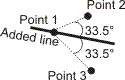
Angle |
Not available |
Not available |
Not available |
|
Not available |
|
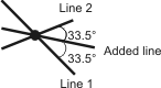
Bisector |
Not available |
|
Not available |
Not available |
|
|
Relative sector |
Not available |
|
Not available |
Not available |
Not available |
|
Parallel |
Not available |
Not available |
Not available |
|
Not available |
|
Perpendicular |
Not available |
Not available |
Not available |
|
Not available |
Base features of a
constructed point feature
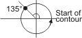
A point is a geometric primitive that represents an X- and Y-position. You can construct points using one of several specialized build operations. The build operation constructs a point that represents a location on a feature or a relationship between features. You can use constructed points to retrieve important results. For example, you might need to measure the diameter of a circle. To do so, use the Relative Position build operation to construct 2 points on the circle: the first at 0% of the circle's contour, and the second at 50% of the circle's contour. Then, define a minimum distance tolerance using these 2 points as base features. The Value result of the DistanceMin tolerance gives you the circle's diameter.
The following table illustrates the build operations and required features to construct points:
|
Build operation (method) |
Base feature(s) used to build the point |
|||
|
Point |
Circle or Arc |
Segment |
Several features |
|
|
Intersection |
Not available |
Not available |
Not available |

|
|
Extended intersection |
Not available |
Not available |
Not available |

|
|
Center |
Not available |
|

|

|
|
Middle |
Not available |
|

|
Not available |
|
Closest |
Not available |
Not available |
Not available |

|
|
Maximum distance |
Not available |
Not available |
Not available |

|
|
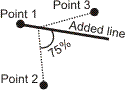
Point and angle |

|
|
Not available |
Not available |
|
Absolute position (length units from X-axis or start position) |
Not available |

|

|
Not available |
|
Relative position (percentage of base feature) |
Not available |

|

|
Not available |
|
Absolute angle (angle from X-axis) |
Not available |
|
Not available |
Not available |
Each build operation constructs one point.
Base features of
constructed edgel features
Edgels are elementary points (or edge elements) within an edge. Each edgel represents an X- and Y-position, and the angular direction of the gradient. An edgel feature contains one or more edgels. You can construct an edgel feature using the Copy feature edgels build operation, which copies the set of edgels from the specified base feature. The specified base feature must be physically measured. For more information, see the (Physically) measured features section later in this chapter.
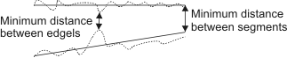
The feature's edgels might prove useful in several types of applications. For example, physically measured segment features are built using a fit operation that is based on edgels in a search region. Geometric tolerances are then applied on the fitted segments, and not the edgels on which they are based. However, you might want to set a true minimum distance tolerance between segments based on the edgels that were used to build them, rather than basing the minimum distance on the best fit segments. This can be done by creating, for each physically measured segment, a constructed edgel feature that contains only the edgels used to build the physically measured feature. Then, you can set the tolerance to the minimum distance between the constructed edgel features.
The following table illustrates the build operation and required features to construct edgels:
|
Build operation (method) |
Base feature(s) used to build the edgel feature |
||||
|
Segment |
Circle |
Arc |
Edgel |
Point |
|
|
Copy feature edgels |

|

|

|

|

|
Note that the distribution of edgels need not resemble the physically measured feature. For example, a segment feature can be built from edgels that resemble a circle.