(Physically) measured features
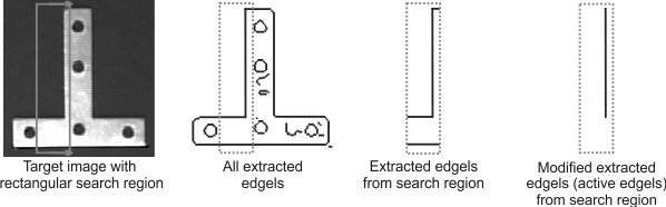
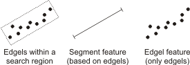
Physically measured features are geometric primitives that the Metrology step extracts from contour pixels (edgels) in a metrology search region. For example, you can define a rectangular search region from which to extract a segment feature.
In general, good results come from tight search regions that only contain one shape. In situations where multiple shapes and edges are very close together or the required shape is not the most strongly contrasted, it might be better to identify shapes using other analysis steps. For example, you can use the Measurement step, EdgeLocator step, BlobAnalysis step, or use a shape finder step (such as the RectangleFinder step, CircleFinder step, EllipseFinder step, or SegmentFinder step).
The following table lists all physically measured features and the search regions from which you can extract them.
|
Search region |
Feature |
||||
|
Point |
Arc |
Circle |
Segment |
Edgel |
|
|
Rectangle |
— |
— |
— |
Yes |
Yes |
|
Segment |
Yes |
— |
— |
— |
— |
|
Arc |
Yes |
— |
— |
— |
— |
|
Ring |
— |
— |
Yes |
— |
Yes |
|
Ring-sector |
— |
Yes |
— |
Yes |
Yes |
 Point feature
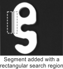
The following methodology shows how to add a physically measured point feature from a segment or arc search region. Features are typically created where the search region intersects with an edge. Note that information on how to define each measured feature is available at design-time, from the Quick Access pane.
-
In the Configuration pane, click on the Add... button in the user-defined features section. Select Measured for the type and either Point (from Segment) or Point (from Arc) for the geometry of the feature and search region. If there is only one type of search region possible for the feature, the search region is not mentioned. Click on the Add button when finished.
-
On the next page:
-
For a Point (from Segment) feature, you can enter Search settings (such as the Polarity, Smoothness, and Threshold values), and Region settings (such as the start and end coordinates of the segment). You can also interactively adjust the segment in the display view.
-
For a Point (from Arc) feature, the settings are similar, except that under the Region settings section, you can adjust the Radius, Start angle, and End angle of the arc.
-
-
Define the search region. When you add a measured feature, Matrox Design Assistant automatically places a search region, which you can resize and reposition. Note that it is often faster to click the Redefine button
 , and
then draw the search region at the required location in the
image.
, and
then draw the search region at the required location in the
image.
In the following example, a point is created wherever the segment intersects an intensity transition (edgel) from dark to bright or from bright to dark.
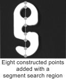
All of these points are part of one point feature. Individual points are indexed so that you can access them (for example, to create other features or tolerances). For a point feature, you can set the Minimum number and Maximum number of transitions to find along the segment's path.
In the following example, points are created along an arc search region (Point (from Arc)), with dark to bright polarity and a Maximum number of 12 transitions.
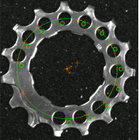
The arc marks the edge of each new intensity change with which it comes in contact. In this example, twelve dark to bright transitions are noticed and marked with points. High smoothing is applied to minimize the effect of the reflections in the image.
Note that when adding a measured feature, you can choose its reference frame. To change the reference frame after defining the feature, select the feature in the Configuration pane, click on the Edit button, and then select a fixture from the Coordinate system dropdown list.
Segment feature
Search region
Each search region has an orientation, which refers to the alignment of the region, with respect to its reference frame. The following example shows 4 search regions (ring, arc, segment, and rectangle) and their orientation, as depicted with an arrow.
By default, physically measured features are typically extracted using all edgels in the feature's search region. However, for unusually complex images, or to fit your application's needs, you might want to restrict which edgels are extracted. To do so, you can use the Polarity, Smoothness, and Data angle tolerance inputs in the Configuration pane. For more information on these inputs, refer to the Customizing edge extraction section later in this chapter.
In addition, advanced inputs, such as FitDistanceMax, are available from the Properties pane. For more information, see the Advanced fit section later in this chapter.
Best fit, inner fit, and
outer fit operations
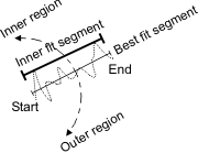
Physically measured features are built by processing the valid edgels in the search region with a best fit (default), inner fit, or outer fit operation. You can change the Build operation from the Configuration pane. Altering the Build operation typically affects the feature that is built.
|
Build operation (method) |
Description |
Feature to build |
||
|
Arc |
Circle |
Segment |
||
|
Best fit |
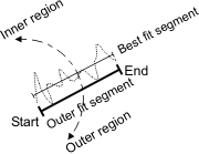
Best fit features pass as close to as many of the edgels as possible. Note that the best fit segment separates the inner and outer fit regions, which are used to calculate the inner and outer fit segments. |

|

|
|
|
Inner fit |
Inner fit features represent the innermost boundary of the edgels. For a circle feature, the inner fit is the largest circle that contains none of the edgels. For a segment feature, the inner fit depends on the best fit segment. The inner fit segment is on the counter-clockwise side of the best fit segment, relative to its direction. The inner fit segment passes through the 2 farthest edgels of the inner fit region such that all the edgels of the inner fit region are located on the same side of the inner fit segment. |
Not available |

|
|
|
Outer fit |
Outer fit features represent the outermost boundary of the set of edgels. For a circle feature, the outer fit is the smallest circle that contains all of the edgels. For a segment feature, the outer fit depends on the best fit segment. The outer fit segment is on the clockwise side of the best fit segment, relative to its direction. The outer fit segment passes through the 2 farthest edgels of the outer fit region such that all the edgels of the outer fit region are located on the same side of the outer fit segment. |
Not available |

|
|
Note that a feature will not necessarily touch the edgels from which it is physically measured.
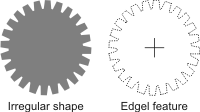
(Physically measured) edgel
features
Unlike other physically measured features, edgel features are not extracted with a fit operation; they are a collection of elementary edge points (or edge elements) inside the search region.
Physically measured edgel features can be useful in analyzing irregular shapes. For example, you can add a feature that does not represent a classic geometric primitive. You can then perform operations on this feature, such as constructing its center of gravity.