
Reference frame
All positional information, for features and search regions, is defined relative to a coordinate system or fixture. The coordinate system or fixture that you use as your reference is called the reference frame.
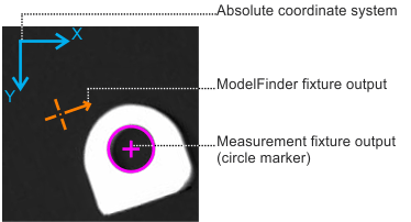
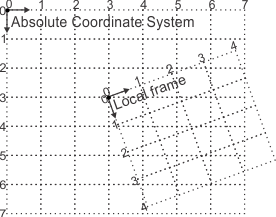
Every parametric feature, physically measured feature, and feature search region has a reference frame with which it is associated. The reference frame can be a fixture output from another step, the absolute coordinate system, or a local frame (user-defined feature). In the image below, several reference frames are identified.
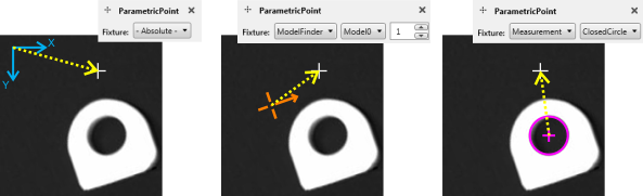
The following images demonstrate defining a parametric point feature relative to different reference frames. From left to right, the specified reference frame is: the absolute coordinate system, a ModelFinder step fixture output, and a Measurement step fixture output.
You can define a local frame to associate features and search regions to a local, user-defined fixture. For example, if a specific part of your image makes a logical reference point, add a local frame at that position. Local frames can also be relative to other fixtures or features to define a more logical location for a reference frame.
Note that, by default, all results are returned relative to the absolute coordinate system. If you want to obtain results relative to a certain point, you can set the global frame to that point and choose to return results relative to the global frame. See the In a Metrology step subsection of the Output coordinate system section in Chapter 32: Fixturing. If you do not require relative position or angle results, it is not recommended to use the global frame.
Constructed features are built from base features and are not associated with a separate reference frame.
If you reposition a reference frame, all features and feature search regions associated with that reference frame are altered accordingly.
 Using
fixtures from other steps to define a reference frame
Using
fixtures from other steps to define a reference frame
You can use a fixture output from a previous step as a reference frame. This is useful if your parts move at runtime, and ensures that associated features and search regions move along with the part.
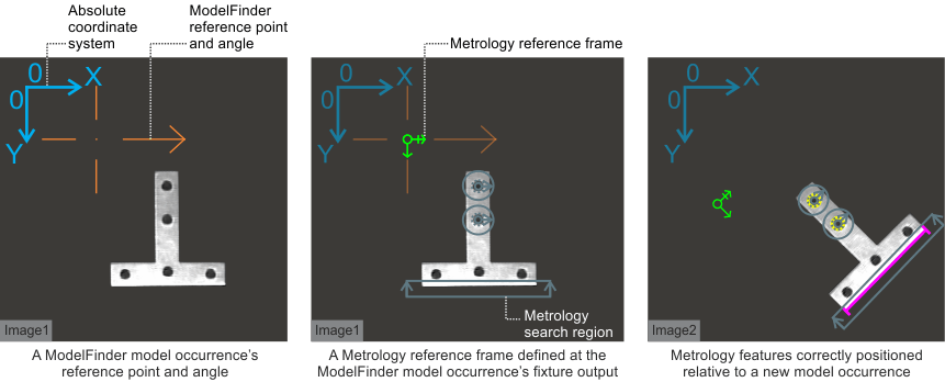
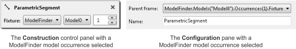
For example, any occurrence of a model found using the ModelFinder step has a fixture output that you can use as a reference frame in the Metrology step. To do so, when adding a new feature, choose the ModelFinder occurrence and fixture from the Construction control panel or, if working from the Configuration pane, select the required occurrence from the Parent frame dropdown list.
Local frame
A local frame is a fixture that only exists inside the Metrology step. If, in your project, there are no suitable reference frames (such as the absolute coordinate system or a fixture output from another step), you can add a local frame. For instance, you might have a Finder step fixture output that is not well-positioned for use as a reference frame. In this case, you can add a local frame relative to the fixture output, and then define required metrology features and search regions relative to the local frame.
You can add parametric or constructed local frames. Note that parametric local frames are added relative to another coordinate system. That is, a parametric local frame has its own reference frame (such as a fixture output from another step). Constructed local frames are defined from base features. If the parent reference frame, or a base feature of the reference frame, moves, the local frame will move as well.
You can add a local frame by defining it directly on the image relative to a selected reference frame, constructing it from 2 points or 1 point and an angle, cloning it from another local frame, or by providing specific position and angle values.
To add local frames, perform the following:
-
Run the project to the Metrology step.
-
Click on the Define local frame (
 ) toolbar button in the
Project toolbar. Then, select from the following:
) toolbar button in the
Project toolbar. Then, select from the following:-
Draw a LocalFrame. Select a fixture from the Construction control panel; then, draw a new local frame directly in the image. Click and hold to set the frame's origin and move your mouse to rotate the frame and then release when finished.
-
Two points. Create the frame from 2 existing base features. The new frame is positioned at the first selected base feature, with the X-axis pointing to the second. You can construct the frame from any 2 points, circles, arcs, or reference frames.
-
Angle. Create the frame from a point and a specific angle.
-
Clone. Copy exactly an existing frame or fixture. Select Advanced, and then Clone.
-
-
To delete a reference frame, click on its callout and select Delete feature from the dropdown list. You can also select the reference frame from the Configuration pane and click on the Delete button.
-
Use the Configuration pane to view your reference frames and ensure that they are correct.
-
You can also use the Configuration pane to move your reference frames or position them based on a linked value.
Alternatively, you can use the Configuration pane to define a new local frame. Click on the Add... button next to the user-defined features section; then, choose to create either a Constructed or Parametric frame. For a constructed frame, the steps are similar to the Two points, Angle, and Clone methods listed above. For a parametric frame, choose a fixture from the Parent frame dropdown list; then, click on the Add button and enter an exact position and angle.
Note that, for features or search regions defined relative to a local frame, any positional changes to these features or search regions should remain relative to the same local frame.