
Procedure for using the Project Change Validator
The following provides an overall methodology for using the Project Change Validator:
-
Deploy your project.
-
Optionally, change the validation server, and if it will receive validation requests from a PLC.
-
Run the project and record inspections (inspection inputs and outputs); then, add the inspections to use for validation to the validation set.
-
Optionally, set up a PLC to automatically receive notifications and request validation whenever changes are made to your project.
-
Request a validation, either manually from the Matrox Design Assistant configuration portal or automatically using a PLC, and wait for it to complete.
-
Review the validation report to determine why your project did or did not pass validation.
-
If your project did not pass validation, modify your project and request another validation.
 Accessing and
setting up the Project Change Validator
Accessing and
setting up the Project Change Validator
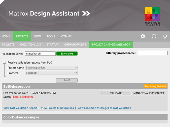
To set up the Project Change Validator:
-
Access the PROJECT CHANGE VALIDATOR tab of the PROJECTS portal page.
-
Optionally, change your validation server, either by name or IP address. By default, it is the runtime platform.
If your validation server is not also the current runtime platform, the Project Change Validator will automatically copy your project and validation set to the validation server immediately before performing each validation.
-
Optionally, enable the Receive validation request from PLC option and specify the Project name of the deployed project for which the PLC will request validations. The Project Change Validator can only receive validation requests from a PLC for the specified project, even if there is more than one project running on your runtime platform.
You can also specify the Protocol that will be used to receive validation requests from the PLC. For more information, see the Validation from PLC section later in this chapter.
Typically, you should not enable the Receive validation request from PLC option if your runtime platform might run projects that communicate with a PLC without using Quick Comm. Communication with the PLC that is not managed by Quick Comm can sometimes be interpreted by the Project Change Validator as a request for validation.
Validation
server
Validation set
A validation set, which is used to validate your project, contains one or more explicitly added inspections that you have recorded. A recorded inspection is the set of inspection inputs and inspection outputs corresponding to one execution of your project's main loop (the steps between the InspectionStart and InspectionEnd points). Recorded inspections are created by recording inspection inputs and inspection outputs after the project has been deployed and is running. You can then add recorded inspections that you would like to use for validation to the validation set.
The following table lists the inspection inputs and inspections
outputs that you can record for validation. These inputs and
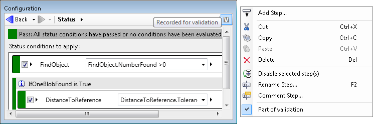
outputs are indicated at design-time with the
Recorded for validation ( )
toolbar button of the
Navigation toolbar of the
Configuration pane.
)
toolbar button of the
Navigation toolbar of the
Configuration pane.
|
Inspection inputs |
Inspection outputs |
|
Images and their calibration data (for example, from the Camera step). |
The results of every Status step and its conditions. |
|
Data received by a NetworkReader step. |
Data sent by a NetworkWriter step. |
|
Data received over EtherNet/IP and PROFINET when using Quick Comm. |
Data sent to a PLC when over EtherNet/IP and PROFINET using Quick Comm. |
|
The current recipe. |
Note that the results of some communication steps, such as the TextReader step, are not included in validation sets. If your project depends on the results of communication steps that are not included in the validation set, the Project Change Validator might not be appropriate for use with your project.
Recording and creating a
validation set
Reduce what is recorded for
validation
You can disable what to record for validation using the
Recorded for validation ()
toolbar button of the
Navigation toolbar, or using the Part of validation context
menu item.
By default, all inspection inputs and inspection outputs that can be enabled for recording will be. You should disable the outputs you do not need to validate.
To enable or disable the recording of data sent to the PLC (when Quick Comm is enabled), you must access the DataToPLC page of the Platform Configuration dialog.
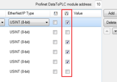
Note that, when recording, data received over EtherNet/IP and PROFINET is always recorded for validation when using Quick Comm.
Requesting
validation and reviewing validation reports
Monitor for
validation
If any of the following occurs with your project, a message is displayed in the PROJECT CHANGE VALIDATOR tab, indicating that you should perform a validation:
-
Changes to operator view inputs.
-
Changes made using the SavePersistentData step.
-
Project deployment.
Optionally, when using Quick Comm, your project can also automatically notify the PLC when such modifications occur, to indicate that validation might be required. For more information, see the Validation from PLC section later in this chapter.
By default, all operator view inputs are monitored for change. You should disable monitoring such inputs when it is not necessary (for example, a text box that logs the name of the operator using it). To disable (or enable) monitoring, click on the Validation toolbar button in the Navigation toolbar of the operator view element's Configuration pane.
Note that, this Validation toolbar button is
the same as the
Recorded for validation ()
toolbar button (in the
Navigation toolbar of a step's
Configuration pane) that was previously discussed. However,
for operator view elements, this button is for enabling or
disabling monitoring.
Also note that, you cannot turn off monitoring for changes in the SavePersistentData step and for project deployment.
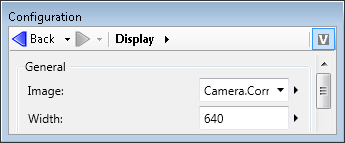
If a Display operator view element is set to be recorded, its content at the end of inspection (including annotations) will be shown in the validation report.