Procedure for using the ModelFinder step
The following procedure provides a basic methodology for using the ModelFinder step:
-
Optionally, adjust the ModelFinder step settings to control the search algorithm's speed and thoroughness.
-
Optionally, adjust the Advanced search settings specific to the ModelFinder step to further control the image data that you will search.
-
Run the project to the ModelFinder step to ensure your project works correctly.
To specifically search for line segments or circular, elliptical, or rectangular shapes in your image, use the SegmentFinder, CircleFinder, EllipseFinder, or RectangleFinder step, respectively.
 Define models
To define models, perform the following:
-
Click on the Add image model (
 )
toolbar button in the
Project toolbar.
)
toolbar button in the
Project toolbar. -
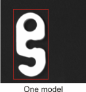
On the image, click the 2 opposite corners of the rectangular region that best surrounds your model. To cancel what you have done, press the Escape key before the last click.
To apply the same setting to multiple models at once, use the Apply multiple dialog, accessible from the setting's Alternate options button.
-
To delete a model, select it from the Configuration pane and press the Delete key.
-
Use the Configuration pane to view your models and ensure that you defined them correctly.
CAD-file
synthetic models
You can add models from DXF files using the Add DXF model
( )
toolbar button.
)
toolbar button.
Matrox Design Assistant supports version 14 2D DXF files. Not every entity in a DXF file is supported; unsupported entities are ignored. The supported entities are Line, Polyline, Lwpolyline, Circle, Arc, Ellipse, Block (a collection of entities), and Insert (an entity containing a reference to where the Block should be drawn, and at what location and scale).
Note that you cannot specify a polarity for a DXF model.
When the model is added from a DXF file, the model will retain its coordinate system (the origin and the axes). Most DXF files are oriented so that the Y-axis is increasing upwards; whereas, the coordinate system Matrox Design Assistant uses is oriented so that the Y-axis is increasing downwards. Therefore, the imaged model will look flipped when compared to the original model. This means that, unless the model is symmetrical, the match will not be made. To avoid this, verify that the Vertical axis input is set appropriately (Flip, No Flip, Default). The default value is Flip.
You can configure the DXF model's reference point when adding the model, or edit the reference point at runtime using the Reconfigure step. A runtime editable annotation is available to allow setting the reference point interactively.
By default, synthetic models are defined to have a 10% margin around the bounding box of their edges. When finding an occurrence, extra edges found in this area will reduce the target score. You can change the size of the margin by setting the Box margin input in the Properties pane. Note also that a synthetic model composed of connected lines, rather than separated line segments, will give more successful results.
For synthetic models, you can specify the Pixel Scale of the model, which is the ratio between pixel units and model (real-world) units. The Pixel Scale input value corresponds to the number of pixels required to represent 1 real-world unit in the DXF model. For example, if 10 pixels represent a distance of 5 mm, the Pixel Scale is 2.0.
When searching for a calibrated model in a calibrated target image, the Pixel Scale only affects the display and draw operations, but not the match nor the returned results. If, after adding a calibrated DXF model, the model's thumbnail image is not what you expect, check the Pixel Scale. The default Pixel Scale for a calibrated model is 1.0/(pixel size in X of the associated camera calibration). In most cases, leave the Pixel Scale at the Default setting for calibrated models.
For an uncalibrated model, you must set a Pixel Scale if the default value of 1.0 is not accurate. In the case of a search for an uncalibrated model in an uncalibrated target image, the Pixel Scale is used for the match.
When searching for synthetic models, if your target image is calibrated, the DXF model must be calibrated. Similarly, if the target image is uncalibrated, the DXF model must be uncalibrated.