Procedure for using the ImageProcessing step
The ImageProcessing step applies one or more operations on one or 2 source images and produces a single output image of a specified size and type.
The following procedure provides a basic methodology for using the ImageProcessing step.
-
Set the Image property. This image will be used to initialize the working buffers ProcessedImage and the OutputImage. See the Images and calibration subsection of this section for more information.
-
Set the Width and Height properties if you need the step's output image to have a different size from the first source image that is used. A different size image is typically needed for geometry and polar operations.
-
Set the Number of bands. For more information, see the Dealing with color images section in Chapter 2: Building a project.
-
Set the OutputImage Type if it differs from the first source type. Types such as Signed16Bits are used to avoid overflows when subtracting 2 8-bit images. If the sign of the difference is not important, you can use the SubtractAbsolute operation and remain with 8-bit images. Unsigned16Bits is used to accumulate a sum or the multiplication of 8-bit images without overflow.
-
If your images will be more than 8 bits, see the Displaying images with more than 8-bits section in the Display view reference chapter for more information.
-
Some Matrox Design Assistant steps require an 8-bit image as their input. If intermediate operations have produced an image with a data depth of 16 bits, you might need to remap the image back to 8 bits. To do so, use the WindowLeveling or Shift operations.
-
Click on the Add button to select a new operation to add to the list. Operations are grouped by category. A short description of the operation is provided when you select it.
-
Operations are appended to the end of the step's list of operations. You can change their location by using the up and down arrows.
-
For a description of each operation, see the ImageProcessing step operations section later in this chapter. For more examples, see Common tasks using the ImageProcessing step.
-
Optionally, specify a region on which to operate on.
-
The checkboxes next to each operation can be used to enable or disable an operation temporarily while experimenting with different approaches.
By default, the source for each image processing operation will be the output image of its predecessor in the list (ProcessedImage). However, you can specify the source image of a step to be any image in the project by linking it.
As an optimization, in situations where you do not need to initialize ProcessedImage and OutputImage (for example all pixels in the output will be set by one of the operations, overwriting any initial values), then you can set Image to None and the initial copy will not be done. Alternatively, enable ClearImage to set the image's pixel values to zero.
 Viewing
intermediate results
Viewing
intermediate results
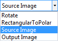
You can also choose to view the output of a specific operation by selecting it from the operations list in the Project toolbar:
Viewing source and
destination images
If your view is set to Split View, Display View, or
External View,
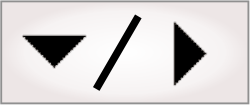
you can use the toolbar buttons in the project toolbar to view
their corresponding image. The Display first source image
(![]() ) and
Display second
source image (
) and
Display second
source image (![]() ) toolbar buttons will display their respective
source images. The Display destination image
(
) toolbar buttons will display their respective
source images. The Display destination image
(![]() )
toolbar button will show the result image after it has been
processed by the selected operation in the list. The destination
image is shown by default.
)
toolbar button will show the result image after it has been
processed by the selected operation in the list. The destination
image is shown by default.
Specifying a
region
Regions of interest (ROI) can be used to specify the portion of an image which the operation should work on. Matrox Design Assistant allows you to specify whether to use the same region for the source(s) and destination, or whether the source and destination will have independent regions. Each operation can have independent regions.
You can specify the regions either interactively or by providing its coordinates. See the Search regions section in Chapter 2: Building a project for more information on how to specify regions.
Defining a
region interactively
To specify the region interactively, you can use the region related toolbar buttons; for example:
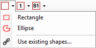
Specifically, you can:
-
Click on the Draw global step region (
 ) toolbar button to use the same region for both
source(s) and destination for all operations, unless it is
overridden. This is the default region for all the sources and
destinations in the step and can be overridden by the other types
of regions.
) toolbar button to use the same region for both
source(s) and destination for all operations, unless it is
overridden. This is the default region for all the sources and
destinations in the step and can be overridden by the other types
of regions. -
Click on the Draw source and destination regions (
 ) toolbar button to override the region specified
by the Draw global
step region toolbar button for the specific operation. With
this option, the same region of the image is used for source(s) and
destination, but only for the selected operation.
) toolbar button to override the region specified
by the Draw global
step region toolbar button for the specific operation. With
this option, the same region of the image is used for source(s) and
destination, but only for the selected operation. -
Click on the Draw destination region (
 ) toolbar button when you need a different region
for source and destination. For example, use this option when
geometry operations affect the size of the region, to compensate
for a displacement between 2 source images (alignment), or to
collage portions of image into one final image.
) toolbar button when you need a different region
for source and destination. For example, use this option when
geometry operations affect the size of the region, to compensate
for a displacement between 2 source images (alignment), or to
collage portions of image into one final image.
In the ImageProcessing step, you cannot use a Fixtured rotated rectangle. Instead, you can use the ImageCorrection step to rotate the pixels instead of rotating the ROI. The difference between the ImageCorrection step and the ImageProcessing step Geometry Rotate operation is that the ImageCorrection step preserves the correct coordinate locations for objects in the transformed image.
Images and
calibration
By default, the step's input image and its associated calibration are used to initialize the data and provide the calibration for the internal buffer called ProcessedImage and the OutputImage. ProcessedImage is the default Source 1 for each operation that is added, hence chaining each operation to the result of the preceding one.
By default, the calibration associated with the OutputImage will be the same as for ProcessedImage. In some cases, for example after geometric operations, pixel values are "moved" to the new image locations and it might be necessary to modify the calibration. The OutputImageCalibration property can be used to specify another calibration which will be associated at the end of the step's execution. See the Chapter 30: Calibration chapter for more information.
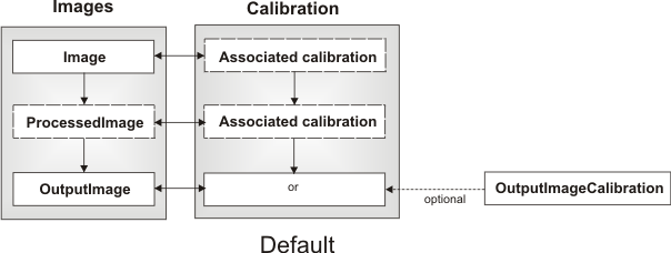
However, if you are working with calibrated images, and Image is set to None, you must specify which calibration should be initially associated with ProcessedImage by specifying the ProcessingCalibration property.
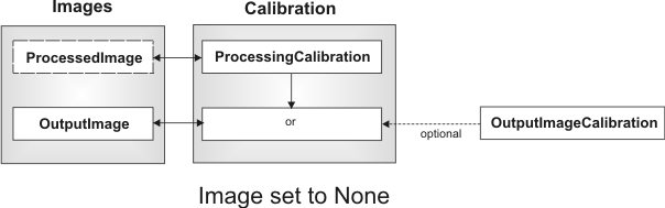
Note that this input is only visible in the Properties pane when Image is set to None.