Procedure for using the BeadInspection step
The following procedure provides a basic methodology for using the BeadInspection step:
-
If you are validating beads that move at runtime, you can link the location of the fixture.
-
Specify the image with which to train the templates.
-
Using the training image, add a template and define its initial points.
-
Optionally, modify an already existing template.
-
Optionally, specify the general settings.
-
Optionally, specify the training settings.
-
Optionally, specify the inspection settings.
-
Run the project to the BeadInspection step to ensure your project works as you expect.
 Training image
The training image is used to add the initial points to the bead template and, subsequently, to train the template (calculate the trained points). A trained template is then used to inspect beads in the target image. Each BeadInspection step must have one training image; all the templates use this image. To specify a training image, perform the following:
-
Select an appropriate image to display. The displayed image will then be set as your training image.
By default, a BeadInspection step displays the target image. You must therefore make sure that the target image on display will make a suitable training image; if not, select a different image.
-
If you are validating beads that move at runtime, link the location of the displayed (target) image's Fixture to the location results of a Fixture provider step, such as the ModelFinder step, the PatternMatching step or the Fixture step. For more information, see the Link the location of the fixture subsection of this section.
Note that the Fixture is the coordinate system in which templates are defined and to which results are relative.
-
Set the currently displayed target image (and its Fixture) as the training image (and its Fixture). To do so, right-click on the training image, and select Set Image as Training image, or click on the Set training image (
 ) toolbar button in the
Project toolbar.
) toolbar button in the
Project toolbar.The first time you add a template, you do not have to click on this button; the currently displayed target image is automatically set as the training image.
By default, the training image's Fixture is the same as the target image's Fixture. Therefore, if your beads move at runtime, you must link the location of the target image's Fixture before setting the target image as the training image. Also, you must run the project to the BeadInspection step for the new Fixture location to take effect; this should be done before setting the training image.
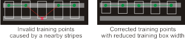
Training in the presence
of nearby stripes
When 2 stripes are close to each other, the BeadInspection step might confuse the stripes, leading to invalid training points. To correct this, reduce the training box width.
Adding a template
and defining its initial points
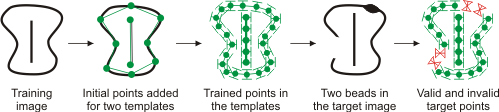
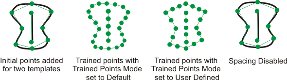
The template represents a reusable model of a valid bead. Templates are created using the initial points that you provide in the training image. Based on these initial points, a group of internally calculated points, along the found bead in the training image, are generated; these trained points make up the template and are used to validate the beads at runtime. Note that automatically determined search boxes are used to locate the trained points along the bead in the image. To control how these trained points are generated, such as the search box size and spacing applied between them, see the Training settings subsection of this section.
You can add multiple templates. Every template in a BeadInspection step is trained according to the step's training image. To add a template and define its initial points, perform the following:
-
Click on the Add template (
 ) toolbar button. This is the fastest way to add
a template and define its initial points (with default
settings).
) toolbar button. This is the fastest way to add
a template and define its initial points (with default
settings). -
Click along the bead's path to add the initial points. By default, a polyline (annotation) is drawn to visually connect the points; each click is one point. Ideally, each initial point should be within the width of the bead; if possible, the annotated polyline should also fall along the bead. To cancel the points you are adding, press the Escape key before the last click.
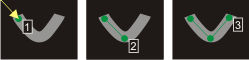
As this image illustrates, the first point added is visually connected (with an arrow) to the Fixture. If the bead is expected to move at runtime, the displayed (target) image's Fixture should be linked to the location results of a locator step, and not to the top-left corner of the image (default). For more information, see the Link the location of the fixture subsection of this section.
Note that if the bead path has an acute angle (0° to 90°), you should add an initial point on either side of the angle's corner.
-
To finish adding points and end the bead's path, you can either hit the enter key, or right-click and select Finish adding points or Close the template polyline.
After you have added the points, the template is validated according to the training image; that is, all the points required to validate the bead are calculated (trained points). Note that the trained points are different than the initial points. All valid and invalid points of the bead in the training image are appropriately annotated. To modify bead annotations, click on the Annotations (
 )
toolbar button.
)
toolbar button.
You can, if required, choose not to use the training image to position the trained points. In the Configuration pane, select the bead to manually train and click Edit, followed by Training settings, and select UserDefined from the Trained points mode dropdown list. This will prevent the BeadInspection step from adjusting the initial points based on the training image. Typically, this should only be done when your initial points are the exact points required to validate the bead. Such points can, for example, come from a CAD file. In this case, the trained points will be positioned along the polyline that connects the initial points.
Additionally, you can disable the Spacing property in the Search boxes for training area immediately underneath. This prevents additional training points from being added along the polyline. This alone will not prevent the adjustment of the initial points.
Modifying a
template
Once a template has been created, it can be modified. To do so, select a template from the Templates section in the Configuration pane. The following options become available:
-
To adjust a single point, you can simply drag-and-drop it in the display image.
-
To add points to the template, click on the Start/stop adding points (
 ) toolbar button.
 -
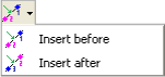
To insert a point before or after a specific point, select a point (either on the image or from the Configuration pane) and click on the Insert point toolbar button.
-
To delete a point in the template, select a point and click on the Delete point (
 ) toolbar button.
 -
To delete all the points in the template, click on the Delete all points (
 ) toolbar button.
 -
To reposition the template (according to the training image's fixture), click on the Translate template (
 ) toolbar button.
 -
To turn the template (according to the training image's fixture), click on the Rotate template (
 ) toolbar button.
 -
To resize the template by a specified factor, click on the Scale template toolbar button.
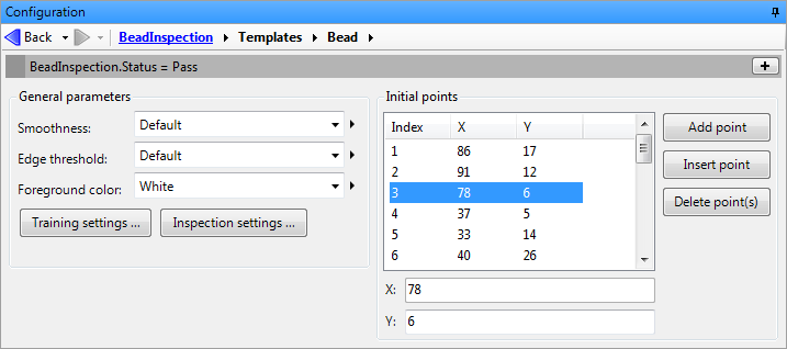
You can also edit each point of a bead more precisely. From the Templates section in the Configuration pane, select the bead to edit and click Edit. In the Initial points area you can select a point, then adjust its x or y co-ordinates manually. Additionally, you can Add point, which appends the bead with a calculated point, Insert point, which inserts a calculated point below the selected point, or Delete point, which deletes the selected point.
General
settings
In either the training or inspection phase, the edges of the bead must be extracted from either the training or target image. The general settings of the BeadInspection step control the edge extraction algorithms. To change the default general settings, perform one or more of the following from the General parameters area of the Configuration pane:
-
Set the Smoothness. Use this to specify the degree of noise reduction to apply to the images. Essentially, this allows you to reduce the number of unwanted edges (noise) extracted from the image. A setting of 0.0 indicates almost no noise reduction effect, while a setting of 100.0 indicates a very strong noise reduction effect. The default is 50.0.
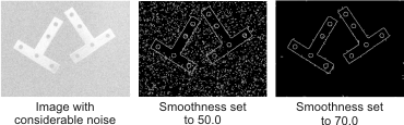
If you experience shiny specular highlights on the bead causing unwanted points (edges) to be extracted, adjusting the smoothness setting can prove useful.
-
Set the Edge threshold. Use this to specify the edge value beneath which a grayscale difference between adjacent points inside the search box (the region used to locate the bead in the target image) are not considered an edge. The default is 10.0.
The edge threshold should rarely be changed. You can try adjusting it if, for example, your image has very low contrast.
-
Set the Foreground color. Use this to specify whether the foreground (bead) is black or white. This value depends on whether the edge to extract (foreground) is darker (black) or lighter (white) than the background.
Training
settings
Training settings are specific to the training phase; these settings affect how the template is built using the training image. The training settings apply to the specified template. All training settings have default values. Typically, they should be changed only when you are inspecting the bead at just a few locations, or when edges or holes that are close to the bead are incorrectly used to add trained points to the template. Note that all applicable training settings are relative to the training image's fixture.
To modify the training settings, perform the following:
-
Select the template from the Templates section in the Configuration pane.
-
Click on the Training settings... button from the Configuration pane.
-
Set the Width and Height of the search boxes. The default width is 200 pixels; the default height is 10 pixels. The width and height values are applied to all search boxes.
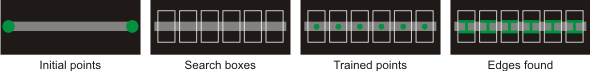
Search boxes are used find the edges of the bead and to calculate the trained points. By default, the trained points are located at the center of bead's edges (width), found within the search box.
-
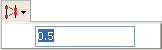
Set the Spacing between the search boxes (trained points). The default is 10 pixels. If disabled, the search boxes are positioned at the initial points only.
-
Set the Nominal width of the bead. That is, only beads with the specified width will be considered for the template. If disabled, the width calculations are not used by the training process, and any bead with the specified foreground color will be considered for the template, regardless of its width.
The width settings for the training phase (Nominal width, Minimum width scale factor, and Maximum width scale factor) should rarely be changed.
-
Set the Minimum width scale factor of the bead. Use this to specify the minimum factor by which a valid bead can be scaled, according to the nominal width.
-
Set the Maximum width scale factor of the bead. Use this to specify the maximum factor by which a valid bead can be scaled, according to the nominal width.
Inspection
settings
Fixture
The fixture is the coordinate system in which templates are defined and to which results are relative. Each BeadInspection step has 2 fixtures: one for the training image (for the training phase), and one for the target image (for the inspection phase). By default, if the image is not calibrated, the fixtures are aligned with the image's top-left corner; otherwise it is aligned with the calibration's origin. Note that if either the target image or training image has a fixture associated with it, a fixture must be explicitly associated with both images.
Link the
location of the fixture
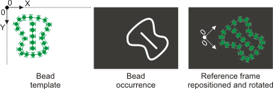
Typically, you must adjust the default fixture if your beads are not at the same position and orientation as the template, which can happen if you are validating beads that move at runtime. In this case, you can link the location of the fixture to the actual position and orientation of the found bead occurrence in a locator step, such as the ModelFinder step or the PatternMatching step.
To position the fixture using the ModelFinder step, follow this basic procedure:
-
From the ModelFinder step, add a model that will be used to fixture the training image. It is preferable for the ModelFinder step to use the image that will become the training image of the BeadInspection step.
-
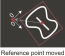
From the ModelFinder step, set the model's reference point to the required origin of the bead template's fixture. By default, the model's reference point is at the center of the model image.
-
From the ModelFinder step, find the model and ensure that the reference point's found position has moved to the required position of the bead's template.
-
From the BeadInspection step, find the Fixture dropdown list in the General parameters area of the Configuration pane. Select the required fixture from the dropdown list.
-
Run the project to the BeadInspection step. The fixture should now have been moved to the found position from the ModelFinder step.
-
From the BeadInspection step, set (or reset) the current image to the training image.
Note that if you have created a training image before starting the above fixture setting procedure, you must re-create the training image to incorporate the new fixture.
To manually adjust the position and orientation of the training image's fixture, click on the Redefine fixture toolbar button while working on the training image.
For more information on using the ModelFinder step, see Chapter 13: ModelFinder step.