Procedure for using the ImageWriter step
 Previous
- Next

The following provides a basic methodology for using the ImageWriter step:
-
Run the project to the ImageWriter step.
-
Specify to save a single image (Save Image) or, if working with 3D data, you can specify to save all available raw 3D components at once (Save 3D Components).
-
Specify the Root file name prefix for the file name.
A timestamp can be embedded into the root file name. This is useful when your application needs to output images based on the current time or the Camera step's GrabTime property. To do so, use the DATETIME function in the Advanced editor Configuration pane to convert a timestamp object to a text string. Note that, when writing a date/time timestamp to a file name, you must use a format that does not include slash characters, ("/" or "\") or other file-system-reserved characters. For more information on possible DATETIME formats, see User-defined date/time and number formats.
-
To automatically number the files in the sequence with a suffix, select the Numbered files option. Then, specify the Start index and an End index suffix. When the last image file is reached, the numbering restarts at the beginning, and the first image of the sequence is over-written.
-
Specify the path to a destination folder. The destination folder can be a shared network folder, an unsecured FTP or HTTP site, or a folder local to your runtime platform. When dealing with a remote folder, specify the target platform's ComputerName ; it cannot be an IP address. On a shared network folder, the path must be in the following format: \\\\MYMACHINE\\MySharedFolder. Note the use of the doubled backslashes in the file path is required when accessing a folder path over a network. The default folder is {PATH("DA Documents")}\\SavedImages. For information on specifying a shared network folder, specifying a non-default local folder, unsecured FTP or HTTP sites, or default file paths, see the Specifying a path section in Appendix A: Expression syntax.
-
To have the current recipe's subfolder appended to the path, select the Append recipe subfolder option. Note that the ImageWriter step must be part of a recipe for this option to change your path. For more information on recipes, see the Chapter 55: Recipes.
-
Set the image's file type to one of the following: JPG, TIF, MIM or BMP. When using a JPG, you can specify a JPEG compression quality, where 100 gives the best quality and largest file sizes. When Save 3D Components is specified, the file type is MIM and cannot be changed.
-
To write information to a text file (a sidecar file) with the same name and path as the image being written, select the Write Sidecar File option. Then, specify the text you want to appear in the sidecar file. Construct the text the same way as when using the TextWriter step, using expressions with links to outputs and variables. For example, this can be used to log setup conditions or results per image.
-
To scale the image to a specific size, select the Resize Image option. Then, specify the Image height and Image width. Note that resizing an image will maintain clear annotations, and is useful for smaller HMI panels. Resize Image is not available when Save 3D Components is specified.
-
To save only a portion of the image, either enter values for the top-left corner (X, Y) and size (in X and in Y) of the Region, or click on the Define a region (
 ) toolbar button in the
Project toolbar to draw a region on the image.
) toolbar button in the
Project toolbar to draw a region on the image. -
Specify annotations.
To add shape and text annotations to your image, click on the Add button in the Configuration pane. You can also set a range of properties, such as the color in which a text annotation is written, dependent on a condition within your application. For further information on how to configure your annotations, see the Displays section in Chapter 50: Customizing the operator view. The annotation functionality in the Display element of the operator view is similar to the ImageWriter step, with one key exception. The ImageWriter step does not support editable annotations.
 ImageWriter
step annotations
ImageWriter
step annotations
The ImageWriter step can annotate the image it saves. There are 2 types of annotations, step annotations and user-defined annotations. The step annotations are based on information from the Analysis and Processing steps in your flowchart, and user-defined annotations are graphics, such as shapes or text, that you define and position.
Note that, when you specify Save 3D Components, only the raw image components from the 3D sensor are saved. You cannot include annotations. To do so, use the Save Image option and save the annotations to a single image.
One use for ImageWriter step user-defined annotations is to embed a date/time timestamp in the image. This is useful as the written images can be annotated with the current time or the Camera step's GrabTime property, allowing for images to be tracked and verified as they traverse the imaging environment. To do so, you can use the DATETIME function to convert a timestamp object to a text string for use in a text annotation in the Advanced editor Configuration pane. For more information on possible DATETIME formats, see the User-defined date/time and number formats section in Appendix A: Expression syntax.
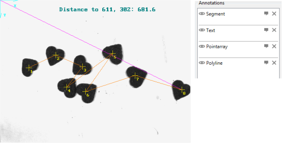
Another use for ImageWriter step annotations is, during design-time, to test complex user-defined annotations destined for the operator view Display element. An operator view only functions during runtime. When the Display element's user-defined annotations are based on a complex expression using array and fixture functions and variables, it is easier to configure the annotation with the feedback at design-time. In this case, copy the Display element's user-defined annotation expressions in an ImageWriter step, view the preview images, and adjust the user-defined annotation accordingly.
The following image demonstrates an example of setting array and other annotations at design-time for preview purposes.