The following procedure provides a basic methodology for using
the PhotometricStereo step.
-
Grab or link images that were captured under the necessary
conditions for photometric stereo.
-
Set which photometric stereo operation(s) to perform by
selecting the required output
images.
-
Optionally, set the remap
factor if some of the source images have peak values that are
much bigger than the others in the set.
-
Set the
light vector type.
-
Optionally, modify the
lighting elements, and the position and relative intensity of
each light source.
-
Optionally, enable
non-uniformity correction for the input images.
-
Optionally, set the timeout
limit for the PhotometricStereo step.
-
Specify any
additional control settings.

 Grab or link
images
Grab or link
images
The photometric stereo source images must be of exactly the same
scene; otherwise, you must align the images before registration.
The images must be taken under different direct lighting
orientations, and are combined in the PhotometricStereo step to
create a single enhanced image.
You can use 4 or more lights in the photometric stereo setup,
whereby each input image must be taken with only one light source.
Note that when setting up for a Local Shape operation, your
lights should be set up in opposite pairs. That is, for each light
in the setup, there should be another light positioned 180 degrees
opposite.
See
Chapter 28: Acquisition for more information about grabbing or
loading an image. See the Photometric
stereo registration of a moving object section later in this
chapter on how to align images if the object is moving.
Note that application notes are available that describe how to
interface Matrox Iris GTR and Matrox 4Sight GPm to some popular
lighting controllers.
Output images
Checkmark one or more required Output Images. This sets
which photometric stereo operation(s) to perform. For information
on each photometric stereo operation, see the Output image types section later in
this chapter.
When multiple Output Images are selected,
you can right-click on the image display and select from the
Display Image context menu item which one to display, or
choose from the dropdown list in the
Project toolbar. For information on displaying multiple
images at once, see the
Displaying multiple images subsection of the
Quick Evaluate pane section in the
Panes and editors reference chapter.
Remap factor
Output images based on shape (Local Shape, Gaussian Curvature,
Mean Curvature)
are calculated internally using normal vectors whose magnitudes can
vary widely depending on image content. Internal calculations are
done in floating-point. However, to generate the output image with
the same depth as the source images, the calculated values must be
mapped or scaled to integer intensity values. By default, the
Remap Factor
input is set to Automatic mode, which remaps
values using the full range of values in the current image. The
remap factor is reported (to the left of the Set button). However, with
some objects and lighting, it is possible for some (but not all)
source images to have peak values that are much bigger than the
others in the set (for example, a random, very sharp reflection),
which causes that image to use a very different remap factor,
possibly diminishing important details in key parts of the image.
To avoid the effect of occasional sharp transitions, you can set a
constant factor to use for the remapping.
Generally, using a constant Remap Factor produces
reliable results. It is recommended to find the reported
Automatic mode
factor for some typical images and then lock in a value
(Set) that is
slightly higher. You can try a value that is 3 to 4 times the
reported Automatic mode factor. This
increases image contrast and helps to bring out smaller details in
the photometric stereo output image.
Light vector
type
For each source image, you must specify the direction of its
light source using a vector.
Set the coordinate system in which you are expressing the source
images' light vectors.
-
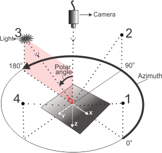
The Spherical
coordinate system defines each light vector with 3 values: the
zenith (polar) angle (angle between a light and the camera), the
azimuth angle (angle of the light vector projected onto the
XY-plane, measured from the positive X-axis), and the relative
light intensity value.
-
The Cartesian
coordinate system defines each light vector with 3 coordinates:
X,Y, and Z, with the axes oriented as shown in the image below.
Note that the origin is located at the center of the plane upon
which the object is placed for the photometric stereo registration
operation, directly below the camera (assuming the camera is
perpendicular to the scene).
Lighting
elements
A lighting element specifies the directional light used to
illuminate one photometric stereo source image. There should be one
lighting element per photometric stereo source image.
Modify the settings of the 4 default Lighting Elements if the
defaults do not match your setup. Add more Lighting Elements if
required.
Ensure that each lighting element is linked to a different
source image.
You must specify your lights in a counter-clockwise order,
starting at the positive X-axis. To illustrate, if you have 4
lights spaced evenly around a scene, and your first light is placed
in line with the X-axis (zero degrees), lights 2, 3, and 4 are
placed at 90, 180, and 270 degrees, respectively, and must be
specified in the same order.
When working in the Spherical coordinate system,
you can modify the relative intensity of each lighting element. The
default value is 1.0. If the relative light intensity is set to 1.0
for all lighting elements, each light provides the same intensity
to the setup, which is the ideal arrangement. If equal light
intensities are not possible, set the strongest light to 1.0 and
set the other light intensity values relative to this.
To adjust relative light intensities within the Cartesian coordinate system,
note that the light intensity correlates to the norm (magnitude) of
the vector formed by X, Y, and Z. Calculate the norm using the
following formula: 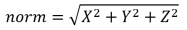 . Once
you know the light intensity for the strongest light, adjust the
X-, Y-, and Z-coordinates of the other lights accordingly.
. Once
you know the light intensity for the strongest light, adjust the
X-, Y-, and Z-coordinates of the other lights accordingly.
Non-uniformity
correction
If a source image's lighting is significantly uneven across the
surface of the scene, enable Non-Uniformity Correction to
see if it improves photometric stereo results.
This setting is recommended only when the image illumination is
severely non-uniform.
The default setting for Non-Uniformity Correction is
Disable. If set
to Auto, source
images are corrected for non-uniform illumination.
Timeout
In certain cases, the PhotometricStereo step might
take longer than is acceptable for your application. To account for
your time constraints, you can set the Timeout property to a
maximum time for the operation. The default Timeout limit is 2000 msec.
If the limit is exceeded, processing is stopped, and no results are
available.
Additional
control settings
Additional controls are available for several photometric stereo
operations.
Shape
smoothness
Output images based on shape (Local Shape, Gaussian Curvature,
Mean Curvature)
are computed using surface normals rather than pixel intensity. For
these output image types, you can control the appearance of small
bumps and hollows on the surface of objects in the scene using the
Shape smoothness
input. Large values apply more smoothing, and result in suppression
of smaller features on an object's surface, making the dominant
structure more prominent. Choose a value between 0.0 and 100.0. The
default is 50.0.
Normalization
The Normalization input is
enabled by default for a Local Shape operation. This
setting (enabled) is often sufficient. However, disabling shape
normalization can improve results if the region undergoing
photometric stereo registration is mostly flat and perpendicular to
the camera. When Normalization is disabled,
small variations of surface normals that are close to vertical will
not be emphasized.
Object size
For a Local
Contrast operation, the Object Size input controls
the number of iterations of an internal morphological operation.
The default is 1 iteration, which can remove artifacts such as
small dots. It is recommended to experiment to find the best
setting for your needs.
Inverting
the grayscale values
By default, raised surfaces are drawn darker in output images
based on shape (Local Shape, Gaussian Curvature,
Mean Curvature).
If you want the inverse (raised surfaces drawn lighter), add an
ImageProcessing
step. Select the required photometric stereo output image to be
processed. Then, apply a Not operation from the
Logic operation
category group.