Procedure for using the ImageCorrection step
 Previous
- Next

The following provides a basic methodology for using the ImageCorrection step:
-
Specify the input Image. If it is associated with a calibration, the output image will be corrected using this information.
-
Optionally, specify a rectangular Region to extract. Use either the Define a region (
 ) toolbar button in the
Project toolbar or the Region... button in the
Configuration pane. For more information, see the
Search regions section in
Chapter 2: Building a project.
) toolbar button in the
Project toolbar or the Region... button in the
Configuration pane. For more information, see the
Search regions section in
Chapter 2: Building a project.The top-left corner of the output image will be the top-left corner of the specified region, rotating the data in the region if the region is specified at an angle. If the input image is associated with a calibration, the image is corrected before the region is extracted. In the latter case, when you draw the region, the region is drawn taking into account the image's calibration, so that the region completely fills the output image.
-
Optionally, specify the Interpolation mode to use during the transformation. This determines the smoothness of edges in the output image.
-
NearestNeighbor has the lowest processing time and produces the roughest edges.
-
Bilinear has a moderate processing time and produces smooth edges.
-
Bicubic has the highest processing time and produces the smoothest edges.
-
-
Optionally, when outputting a corrected version of the whole image, you might want to control the correction mode and output image size.
-
Optionally, specify the Overscan mode. This determines how to handle pixels of the output image that don't have a corresponding pixel in the input image. If Clear is selected (the default), these pixels in the output image will be black. If Enabled or Disabled are selected, these pixels will retain their values from the last time the ImageCorrection step was executed.
In most cases, the Overscan mode should be set to Clear. However, other Overscan modes might provide a minor performance improvement.
 Correction
mode and size when outputting the whole image
Correction
mode and size when outputting the whole image
When outputting a corrected version of the whole image, you might want to control the correction mode and size of the output image.
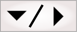
When the calibration of the input image rotates an object that almost completely fills the image, it might not fit in the output image, if the output image size is kept at that of the input image. You can choose from 2 methods of compensating for this using the Correction mode property. You can choose to increase the size of the output image so it fits the entire the input image (ScaleToFitInOutputImage), or to keep the largest rectangular portion of the rotated image that contains no overscan pixels (Clip).
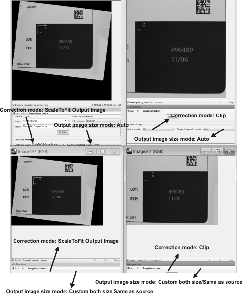
The images above show the resulting output images for the following settings:
-
Setting the Correction mode to ScaleToFitOutputImage and the Output image size mode to Auto will enlarge the output image to the bounding box of the rotated, non-scaled source, and this size will change depending on the degree of rotation.
-
Setting the Correction mode to ScaleToFitOutputImage and the Output image size mode to CustomBothSize/SameAsSource, will produce an output image that has the same size as the source. This mode is not recommended when the image contains small text or fine lines (for example, very small 1D bar codes).
-
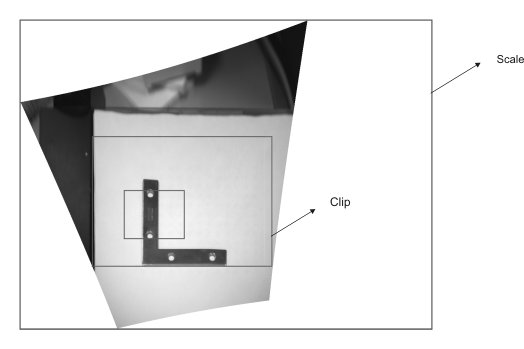
Setting the Correction mode to Clip and the Output image size mode to Auto will produce an image of variable size, equal to the largest rectangle without overscan as shown in the first diagram in this section.
-
Setting the Correction mode to Clip and the Output image size mode to CustomBothSize/SameAsSource will produce an output of a known size. Scales the result of the previous case to the size of the original image.
Note that if you want to explicitly specify the output image size, you must do so in pixels.