Modbus example
 Previous
- Next

Consider a simple example where the PLC sends a part identifier number (P/N) and sets a trigger bit to indicate that it is time to grab the image. In the example, the project returns a PASS bit and a FAIL bit; they will both be cleared to 0 when the trigger bit is detected, and they will have opposite values based on the result of the Status step at the end of processing. The project will also return the X-coordinate, Y-coordinate, and radius values of a detected circle.
Assume the following is the PLC data map. Coils and holding registers are both read from and written to, and have both input and output values. Note that the Matrox Design Assistant offsets are 1-based and inputs and outputs are from the perspective of the PLC.
|
Coils data table |
|||
|
Field Name |
Direction |
PLC data map offset |
Matrox Design Assistant offset |
|
Trigger |
Output |
0 |
1 |
|
Reserved |
N/A |
1...7 |
N/A |
|
Pass |
Input |
8 |
9 |
|
Fail |
Input |
9 |
10 |
|
Holding registers data table |
|||
|
Field Name |
Direction |
PLC data map offset |
Matrox Design Assistant offset |
|
PartID |
Output |
0 |
1 |
|
Reserved |
N/A |
1...7 |
N/A |
|
X |
Input |
8 |
9 |
|
Y |
Input |
9 |
10 |
|
Radius |
Input |
10 |
11 |
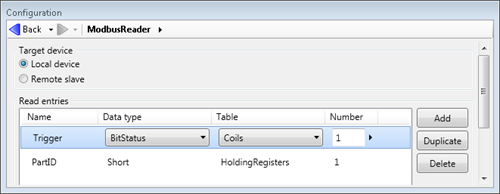
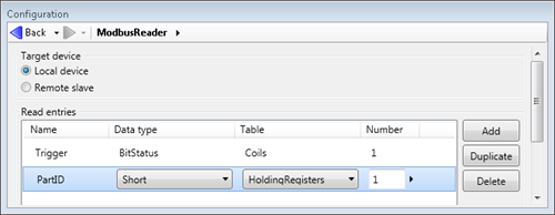
The values read by the Matrox Design Assistant project are one coil entry and one holding register entry, as defined in the ModbusReader step.
The values written by the Matrox Design Assistant project are 2 coil entries and 3 holding register entries, as defined in the ModbusWriter step. Note that the entry names do not have to be identical, although it is good practice.
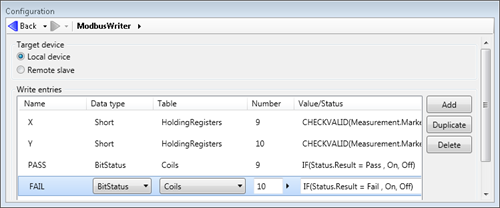
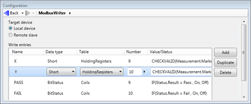
Note that Coil number and Register number are set to the Matrox Design Assistant offsets.
The image below displays the Matrox Design Assistant project flowchart.
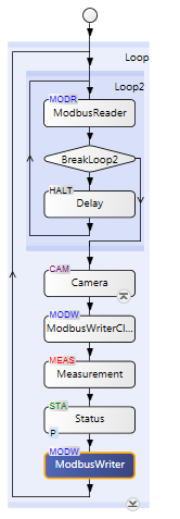
Note that the flowchart waits for the trigger bit to be set before breaking out of the wait loop and proceeding to the Camera step.